
modelOneFloor_OneZone
Extends from Modelica.Icons.Example (Icon for runnable examples).
Information
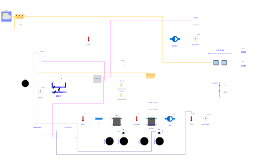
This is a model of a building that has multiple thermal zones on each floor, and an HVAC system on each floor.
The HVAC system is a variable air volume (VAV) system with economizer and a heating and cooling coil in the air handler unit (AHU). There is also a reheat coil and an air damper in each zone inlet branch. Each floor has one VAV AHU system. The figure below shows the schematic diagram of the HVAC system

The control sequence regulates the supply fan speed to ensure a
prescribed pressure rise of 850 Pa when the supply fan runs
during operation modes occupied, unoccupied night set back,
unoccupied warm-up, and unoccupied pre-cool.
The heating coil valve, outside air damper, and cooling coil valve are
modulated in sequence to maintain the supply air temperature set point.
The economizer control ensures the following functions:
minimum outside air requirement, and supply air cooling, see
Buildings.Examples.VAVReheat.BaseClasses.Controls.Economizer.
The controller of the terminal units tracks the room air temperature set point
based on a "single maximum" logic, see
Buildings.Examples.VAVReheat.BaseClasses.Controls.RoomVAV.
There is also a finite state machine that transitions the mode of operation of the HVAC system between the modes occupied, unoccupied off, unoccupied night set back, unoccupied warm-up, and unoccupied pre-cool. Local loop control is implemented using proportional and proportional-integral controllers, while the supervisory control is implemented using a finite state machine.
The thermal room model computes transient heat conduction through walls, floors, and ceilings and long-wave radiative heat exchange between surfaces. The convective heat transfer coefficient is computed based on the temperature difference between the surface and the room air. There is also a layer-by-layer short-wave radiation, long-wave radiation, convection, and conduction heat transfer model for the windows. The model is similar to the Window 5 model and described in TARCOG 2006.
Each thermal zone can have air flow from the HVAC system, through leakages of the building envelope.
References
ASHRAE. Sequences of Operation for Common HVAC Systems. ASHRAE, Atlanta, GA, 2006.
Deru M., K. Field, D. Studer, K. Benne, B. Griffith, P. Torcellini, M. Halverson, D. Winiarski, B. Liu, M. Rosenberg, J. Huang, M. Yazdanian, and D. Crawley. DOE commercial building research benchmarks for commercial buildings. Technical report, U.S. Department of Energy, Energy Efficiency and Renewable Energy, Office of Building Technologies, Washington, DC, 2009.
TARCOG 2006: Carli, Inc., TARCOG: Mathematical models for calculation of thermal performance of glazing systems with our without shading devices, Technical Report, Oct. 17, 2006.
Parameters
| Type | Name | Default | Description |
|---|---|---|---|
| Integer | nZon | 1 | Number of zones per floor |
| Integer | nFlo | 1 | Number of floors |
| Modelica.Units.SI.PressureDifference | dP_pre | 850 | Prescribed pressure difference |
| Modelica.Units.SI.Volume[nZon,nFlo] | VRoo | {{6*8*2.7 for j in 1:nFlo} for i in 1:nZon} | Room volume |
| Modelica.Units.SI.MassFlowRate[nZon,nFlo] | m_flow_nominal_each | 7*conv*VRoo[:, :] | Nominal flow rate to each zone |
| Modelica.Units.SI.MassFlowRate | m_flow_nominal | nZon*(7*conv)*6*8*2.7 | Nominal system flow rate |
| Real | conv | 1.2/3600 | Conversion factor for nominal mass flow rate |
Connectors
| Type | Name | Default | Description |
|---|---|---|---|
| Buildings.BoundaryConditions.WeatherData.Bus | weaBus | Weather Data Bus | |
| Buildings.Examples.ScalableBenchmarks.BuildingVAV.BaseClasses.ControlBus[nFlo] | controlBus | Control bus for each floor |
Components
Contents
| Name | Description |
|---|---|
 MediumA MediumA | |
 MediumW MediumW | Medium model for water |
Revisions
-
March 4, 2024, by Michael Wetter:
Corrected wrong use ofdisplayUnitattribute. -
April 27, 2023, by Michael Wetter:
Reformulated assignment ofm_flow_eachto avoid in Dymola 2023x the error "Incompatible number of dimensions for variable and its definition equation".
This is for issue #3360. -
August 22, 2022, by Hongxiang Fu:
ReplacedfanRet[]with a preconfigured fan model. This is for issue #2668. -
June 17, 2022, by Hongxiang Fu:
Changedfan[].m_flow_nominalfrom 10 to 0.1.
This is for issue #3067. -
June 30, 2021, by Antoine Gautier:
Changed cooling coil model. This is for issue #2549. -
February 25, 2021, by Baptiste Ravache:
Inverse the sign of hex[nFlo].Q_flow_nominal to respect the heat flow convention. -
October 27, 2020, by Antoine Gautier:
Refactored the model for compatibility with the updated control of supply air temperature. This is for #2024. -
October 24, 2017, by Michael Wetter:
Updated model for new fan controller that takes the on/off signal as an input. -
June 6, 2017, by Jianjun Hu:
First implementation.