
modelSystem3
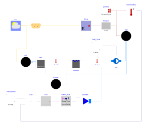
Extends from Modelica.Icons.Example (Icon for runnable examples).
Information
This part of the system model modifies Buildings.Examples.Tutorial.SpaceCooling.System2 to use the actual outside temperature for a summer day, and it adds closed loop control. The closed loop control measures the room temperature and switches the chilled water flow rate on or off.
Implementation
This section describes how we modified Buildings.Examples.Tutorial.SpaceCooling.System2 to build this model.
-
The first step was to copy the model Buildings.Examples.Tutorial.SpaceCooling.System2.
-
Next, we changed in
weaDatthe parameter that determines whether the outside dry bulb temperature is used from the weather data file or set to a constant value. This can be accomplished in the GUI of the weather data reader as follows:
With this change to using real weather data, we also change the simulation time to be one day during the summer, where the start time is 4320 h (15552000 s) and the stop time is 4344 h (15638400 s).
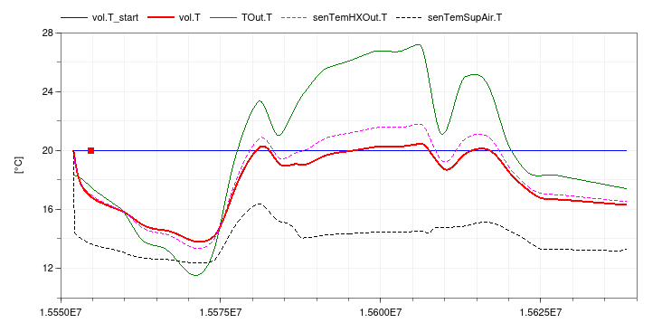
If the model is now simulated, the following plot could be generated that shows that the room is cooled too much due to the open loop control:
To add closed loop control, we proceeded as follows.
-
First, we made an instance of Buildings.Controls.OBC.CDL.Reals.Subtract and set its name to
sub. It calculates the difference between the set point and the measured temperature. -
For the set point, we made the instance
TRooSetPoito feed a constant set point into the instancesub. -
The output of the instance
subwas then fed as the input tocon, which is an instance of Buildings.Controls.OBC.CDL.Reals.Hysteresis. For the instancecon, we set the parameter for the lower limit to -0.5 and the upper limit to 0.5. -
The instance
senTemRoohas been added to measure the room air temperature. Note that we decided to measure directly the room air temperature. If we would have used a temperature sensor in the return air stream, then its temperature would never change when the mass flow rate is zero, and hence it would not measure how the room temperature changes when the fan is off. -
Since the controller output is a boolean signal, but the instance
souWatneeds a real signal as an input for the water mass flow rate, we needed to add a conversion block. We therefore replaced the instancemWat_flowfrom a constant block to the block Buildings.Controls.OBC.CDL.Conversions.BooleanToReal. Because the cooling control has a reverse action, i.e., if the measured value exceeds the set point, the system should switch on instead of off, we configured the parameters of the conversion block as follow:realTrue=0 realFalse=mW_flow_nominal
This will output
mW_flow_nominalwhen the room temperature is above the set point, and 0 otherwise.
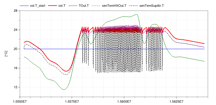
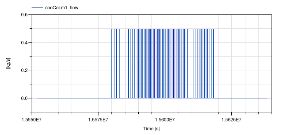
This completes building the model shown in the figure on Buildings.Examples.Tutorial.SpaceCooling. When simulating the model, the response shown below should be seen.
Notes
To add a continuous controller for the coil water flow rate, we could have used the model Buildings.Controls.OBC.CDL.Reals.PID.
Parameters
| Type | Name | Default | Description |
|---|---|---|---|
| Modelica.Units.SI.Volume | V | 6*10*3 | Room volume |
| Real | eps | 0.8 | Heat recovery effectiveness |
| Modelica.Units.SI.Temperature | TASup_nominal | 291.15 | Nominal air temperature supplied to room |
| Modelica.Units.SI.DimensionlessRatio | wASup_nominal | 0.012 | Nominal air humidity ratio supplied to room [kg/kg] assuming 90% relative humidity |
| Modelica.Units.SI.Temperature | TRooSet | 297.15 | Nominal room air temperature |
| Modelica.Units.SI.Temperature | TOut_nominal | 303.15 | Design outlet air temperature |
| Modelica.Units.SI.Temperature | THeaRecLvg | TOut_nominal - eps*(TOut_nominal - TRooSet) | Air temperature leaving the heat recovery |
| Modelica.Units.SI.DimensionlessRatio | wHeaRecLvg | 0.0135 | Air humidity ratio leaving the heat recovery [kg/kg] |
| Modelica.Units.SI.HeatFlowRate | QRooInt_flow | 1000 | Internal heat gains of the room |
| Modelica.Units.SI.HeatFlowRate | QRooC_flow_nominal | -QRooInt_flow - 10E3/30*(TOut_nominal - TRooSet) | Nominal cooling load of the room |
| Modelica.Units.SI.MassFlowRate | mA_flow_nominal | 1.3*QRooC_flow_nominal/1006/(TASup_nominal - TRooSet) | Nominal air mass flow rate, increased by factor 1.3 to allow for recovery after temperature setback |
| Modelica.Units.SI.TemperatureDifference | dTFan | 2 | Estimated temperature raise across fan that needs to be made up by the cooling coil |
| Modelica.Units.SI.HeatFlowRate | QCoiC_flow_nominal | mA_flow_nominal*(TASup_nominal - THeaRecLvg - dTFan)*1006 + mA_flow_nominal*(wASup_nominal - wHeaRecLvg)*2458.3e3 | Cooling load of coil, taking into account outside air sensible and latent heat removal |
| Modelica.Units.SI.Temperature | TWSup_nominal | 285.15 | Water supply temperature |
| Modelica.Units.SI.Temperature | TWRet_nominal | 289.15 | Water return temperature |
| Modelica.Units.SI.MassFlowRate | mW_flow_nominal | -QCoiC_flow_nominal/(TWRet_nominal - TWSup_nominal)/4200 | Nominal water mass flow rate |
Connectors
| Type | Name | Default | Description |
|---|---|---|---|
| BoundaryConditions.WeatherData.Bus | weaBus |
Components
Contents
| Name | Description |
|---|---|
 MediumA MediumA | Medium for air |
 MediumW MediumW | Medium for water |
Revisions
-
April 9, 2024, by Hongxiang Fu:
SpecifiednominalValuesDefineDefaultPressureCurve=truein the mover component to suppress a warning. This is for #3819. -
December 11, 2023, by Jianjun Hu:
Reimplemented on-off control to avoid using the obsoleteOnOffController. This is for #3595. -
September 20, 2021 by David Blum:
Correct supply and return water parameterization.
Use design conditions for UA parameterization in cooling coil.
Use explicit calculation of sensible and latent load to determine design load on cooling coil.
This is for #2624. -
January 28, 2015 by Michael Wetter:
Added thermal mass of furniture directly to air volume. This avoids an index reduction. -
December 22, 2014 by Michael Wetter:
RemovedModelica.Fluid.Systemto address issue #311. -
January 11, 2012, by Michael Wetter:
First implementation.