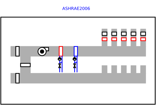
modelASHRAE2006
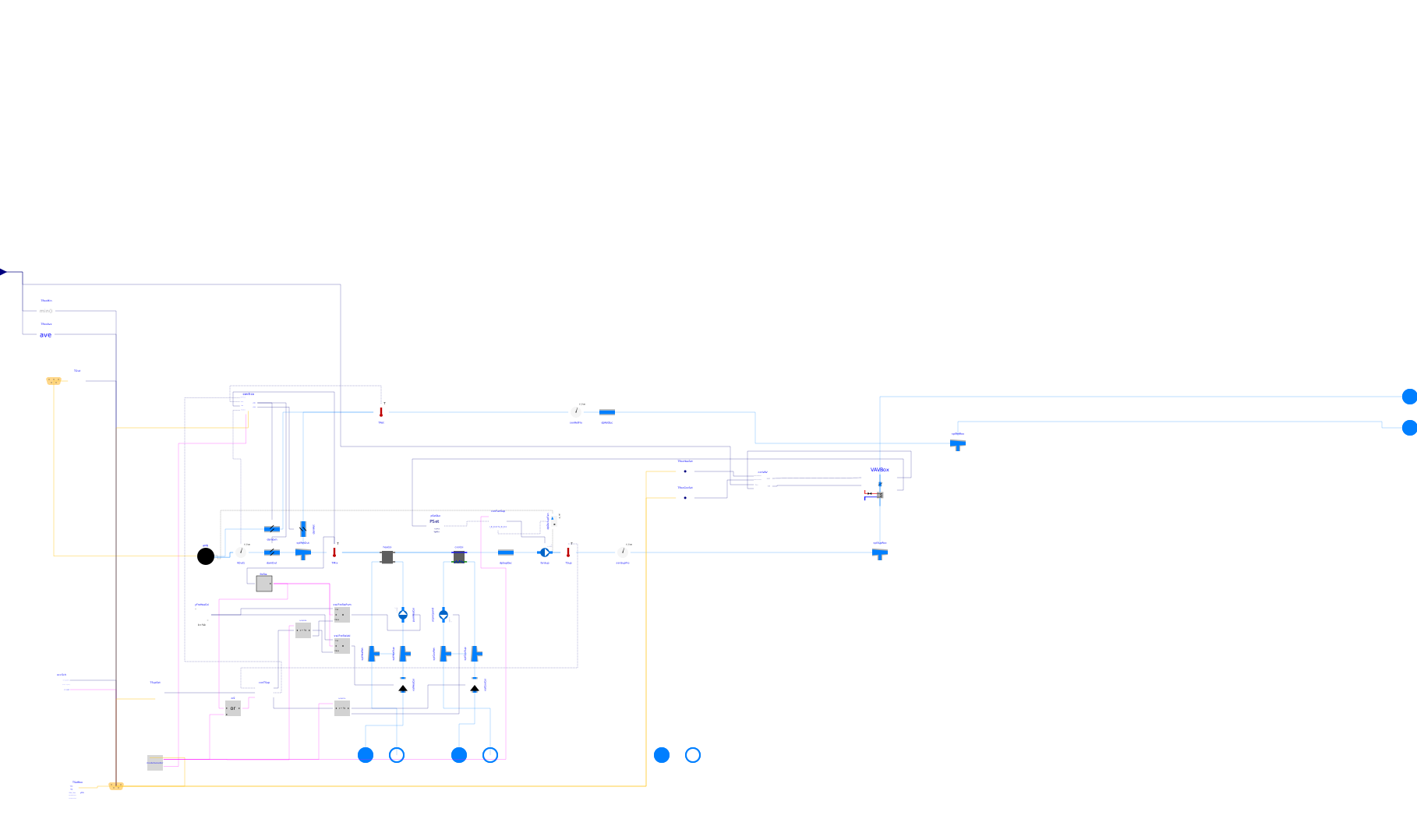
Extends from Buildings.Examples.VAVReheat.BaseClasses.PartialHVAC (Partial model of variable air volume flow system with terminal reheat that serves five thermal zones).
Information
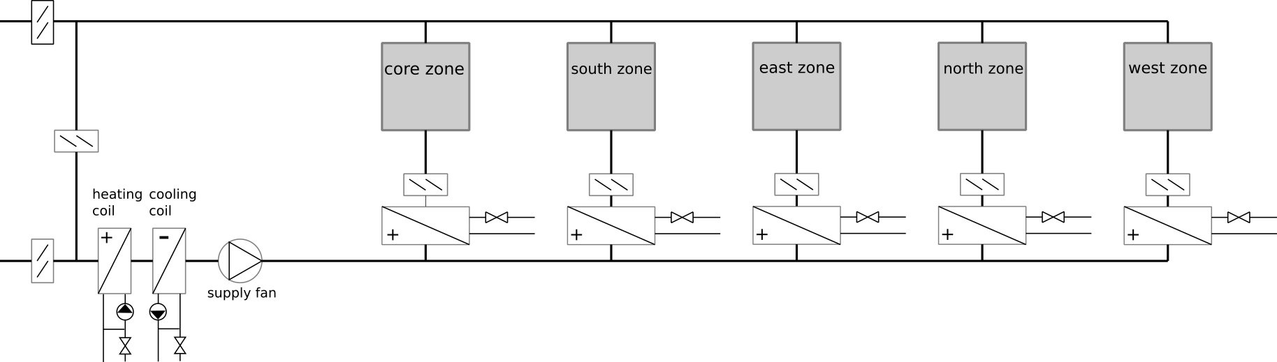
This model consist of an HVAC system is a variable air volume (VAV) flow system with economizer and a heating and cooling coil in the air handler unit. There is also a reheat coil and an air damper in each of the five zone inlet branches. The figure below shows the schematic diagram of an HVAC system that supplies 5 zones:
See the model Buildings.Examples.VAVReheat.BaseClasses.PartialHVAC for a description of the HVAC system.
The control is an implementation of the control sequence VAV 2A2-21232 of the Sequences of Operation for Common HVAC Systems (ASHRAE, 2006). In this control sequence, the supply fan speed is modulated based on the duct static pressure. The return fan controller tracks the supply fan air flow rate. The duct static pressure set point is adjusted so that at least one VAV damper is 90% open. The heating coil valve, outside air damper, and cooling coil valve are modulated in sequence to maintain the supply air temperature set point. The economizer control provides the following functions: freeze protection, minimum outside air requirement, and supply air cooling, see Buildings.Examples.VAVReheat.BaseClasses.Controls.Economizer. The controller of the terminal units tracks the room air temperature set point based on a "dual maximum with constant volume heating" logic, see Buildings.Examples.VAVReheat.BaseClasses.Controls.RoomVAV.
There is also a finite state machine that transitions the mode of operation of the HVAC system between the modes occupied, unoccupied off, unoccupied night set back, unoccupied warm-up and unoccupied pre-cool. In the VAV model, all air flows are computed based on the duct static pressure distribution and the performance curves of the fans. Local loop control is implemented using proportional and proportional-integral controllers, while the supervisory control is implemented using a finite state machine.
A similar model but with a different control sequence can be found in Buildings.Examples.VAVReheat.BaseClasses.Guideline36.
References
ASHRAE. Sequences of Operation for Common HVAC Systems. ASHRAE, Atlanta, GA, 2006.
Parameters
| Type | Name | Default | Description |
|---|---|---|---|
| Integer | numZon (from PartialHVAC) | 5 | Total number of served VAV boxes |
| Modelica.Units.SI.Volume[numZon] | VRoo (from PartialHVAC) | Room volume per zone | |
| Modelica.Units.SI.Area[numZon] | AFlo (from PartialHVAC) | Floor area per zone | |
| Modelica.Units.SI.Area | ATot (from PartialHVAC) | sum(AFlo) | Total floor area for all zone |
| Real | conv (from PartialHVAC) | 1.2/3600 | Conversion factor for nominal mass flow rate |
| Modelica.Units.SI.HeatFlowRate | QHeaAHU_flow_nominal (from PartialHVAC) | mHeaAir_flow_nominal*cpAir*(THeaAirSup_nominal - THeaAirMix_nominal) | Nominal heating heat flow rate of air handler unit coil |
| Modelica.Units.SI.HeatFlowRate | QCooAHU_flow_nominal (from PartialHVAC) | 1.3*mCooAir_flow_nominal*cpAir*(TCooAirSup_nominal - TCooAirMix_nominal) | Nominal total cooling heat flow rate of air handler unit coil (negative number) |
| Real | ratOAFlo_A (from PartialHVAC) | 0.3e-3 | Outdoor airflow rate required per unit area |
| Real | ratOAFlo_P (from PartialHVAC) | 2.5e-3 | Outdoor airflow rate required per person |
| Real | ratP_A (from PartialHVAC) | 5e-2 | Occupant density |
| Real | effZ (from PartialHVAC) | 0.8 | Zone air distribution effectiveness (limiting value) |
| Real | divP (from PartialHVAC) | 0.7 | Occupant diversity ratio |
| Modelica.Units.SI.VolumeFlowRate[numZon] | VZonOA_flow_nominal (from PartialHVAC) | (ratOAFlo_P*ratP_A + ratOAFlo_A)*AFlo/effZ | Zone outdoor air flow rate of each VAV box |
| Modelica.Units.SI.VolumeFlowRate | Vou_flow_nominal (from PartialHVAC) | (divP*ratOAFlo_P*ratP_A + ratOAFlo_A)*sum(AFlo) | System uncorrected outdoor air flow rate |
| Real | effVen (from PartialHVAC) | if divP < 0.6 then 0.88*divP + 0.22 else 0.75 | System ventilation efficiency |
| Modelica.Units.SI.VolumeFlowRate | Vot_flow_nominal (from PartialHVAC) | Vou_flow_nominal/effVen | System design outdoor air flow rate |
| Modelica.Units.SI.PressureDifference | dpBuiStaSet (from PartialHVAC) | 12 | Building static pressure |
| Real | yFanMin (from PartialHVAC) | 0.1 | Minimum fan speed |
| Boolean | allowFlowReversal (from PartialHVAC) | true | = false to simplify equations, assuming, but not enforcing, no flow reversal |
| Real[numZon] | ratVMinVAV_flow | {max(1.5*VZonOA_flow_nominal[i]/mCooVAV_flow_nominal[i]/1.2, 0.15) for i in 1:numZon} | Minimum discharge air flow rate ratio |
| Nominal mass flow rate | |||
| Modelica.Units.SI.MassFlowRate[numZon] | mCooVAV_flow_nominal (from PartialHVAC) | Design mass flow rate per zone for cooling | |
| Modelica.Units.SI.MassFlowRate[numZon] | mHeaVAV_flow_nominal (from PartialHVAC) | 0.3*mCooVAV_flow_nominal | Design mass flow rate per zone for heating |
| Modelica.Units.SI.MassFlowRate | mAir_flow_nominal (from PartialHVAC) | mCooAir_flow_nominal | Nominal mass flow rate for fan |
| Modelica.Units.SI.MassFlowRate | mCooAir_flow_nominal (from PartialHVAC) | 0.7*sum(mCooVAV_flow_nominal) | Nominal mass flow rate for fan |
| Modelica.Units.SI.MassFlowRate | mHeaAir_flow_nominal (from PartialHVAC) | 0.7*sum(mHeaVAV_flow_nominal) | Nominal mass flow rate for fan |
| Modelica.Units.SI.MassFlowRate | mHeaWat_flow_nominal (from PartialHVAC) | QHeaAHU_flow_nominal/cpWat/10 | Nominal water mass flow rate for heating coil in AHU |
| Modelica.Units.SI.MassFlowRate | mCooWat_flow_nominal (from PartialHVAC) | QCooAHU_flow_nominal/cpWat/(-6) | Nominal water mass flow rate for cooling coil |
| Room temperature setpoints | |||
| Modelica.Units.SI.Temperature | THeaOn (from PartialHVAC) | 293.15 | Heating setpoint during on |
| Modelica.Units.SI.Temperature | THeaOff (from PartialHVAC) | 285.15 | Heating setpoint during off |
| Modelica.Units.SI.Temperature | TCooOn (from PartialHVAC) | 297.15 | Cooling setpoint during on |
| Modelica.Units.SI.Temperature | TCooOff (from PartialHVAC) | 303.15 | Cooling setpoint during off |
| Air handler unit nominal temperatures and humidity | |||
| Modelica.Units.SI.Temperature | TCooAirMix_nominal (from PartialHVAC) | 303.15 | Mixed air temperature during cooling nominal conditions (used to size cooling coil) |
| Modelica.Units.SI.Temperature | TCooAirSup_nominal (from PartialHVAC) | 285.15 | Supply air temperature during cooling nominal conditions (used to size cooling coil) |
| Modelica.Units.SI.MassFraction | wCooAirMix_nominal (from PartialHVAC) | 0.017 | Humidity ratio of mixed air at a nominal conditions used to size cooling coil (in kg/kg dry total) |
| Modelica.Units.SI.Temperature | TCooWatInl_nominal (from PartialHVAC) | 279.15 | Cooling coil nominal inlet water temperature |
| Modelica.Units.SI.Temperature | THeaAirMix_nominal (from PartialHVAC) | 277.15 | Mixed air temperature during heating nominal conditions (used to size heating coil) |
| Modelica.Units.SI.Temperature | THeaAirSup_nominal (from PartialHVAC) | 285.15 | Supply air temperature during heating nominal conditions (used to size heating coil) |
| Modelica.Units.SI.Temperature | THeaWatInl_nominal (from PartialHVAC) | Reheat coil nominal inlet water temperature | |
Connectors
| Type | Name | Default | Description |
|---|---|---|---|
| Modelica.Fluid.Interfaces.FluidPort_a[numZon] | port_supAir (from PartialHVAC) | Supply air to thermal zones | |
| Modelica.Fluid.Interfaces.FluidPort_a[numZon] | port_retAir (from PartialHVAC) | Return air from thermal zones | |
| Modelica.Blocks.Interfaces.RealInput[numZon] | TRoo (from PartialHVAC) | Room temperatures | |
| BoundaryConditions.WeatherData.Bus | weaBus (from PartialHVAC) | Weather data bus | |
| Modelica.Fluid.Interfaces.FluidPort_a | portHeaCoiSup (from PartialHVAC) | Heating coil loop supply | |
| Modelica.Fluid.Interfaces.FluidPort_b | portHeaCoiRet (from PartialHVAC) | Heating coil loop return | |
| Modelica.Fluid.Interfaces.FluidPort_a | portHeaTerSup (from PartialHVAC) | Terminal heat loop supply | |
| Modelica.Fluid.Interfaces.FluidPort_b | portHeaTerRet (from PartialHVAC) | Terminal heat loop return | |
| Modelica.Fluid.Interfaces.FluidPort_a | portCooCoiSup (from PartialHVAC) | Cooling coil loop supply | |
| Modelica.Fluid.Interfaces.FluidPort_b | portCooCoiRet (from PartialHVAC) | Coolin coil loop return | |
| Controls.ControlBus | controlBus |
Components
Revisions
-
May 22, 2026, by Michael Wetter:
Changed hardcoded value for number of inputs inpSetDucto use parameternumZon.
This is for issue #4609. -
March 4, 2024, by Michael Wetter:
Corrected wrong use ofdisplayUnit. -
December 20, 2021, by Michael Wetter:
Changed parameter declarations for issue #2829. -
November 9, 2021, by Baptiste:
Vectorized the terminal boxes to be expanded to any number of zones.
This is for issue #2735. -
October 4, 2021, by Michael Wetter:
Refactored Buildings.Examples.VAVReheat and its base classes to separate building from HVAC model.
This is for issue #2652. -
September 16, 2021, by Michael Wetter:
Removed assignment of parameterlatas this is now obtained from the weather data reader.
This is for IBPSA, #1477. -
September 3, 2021, by Michael Wetter:
Updated documentation.
This is for issue #2600. -
August 24, 2021, by Michael Wetter:
Changed model to include the hydraulic configurations of the cooling coil, heating coil and VAV terminal box.
This is for issue #2594. -
May 6, 2021, by David Blum:
Change tofrom_dp=falsefor exhaust air damper.
This is for issue #2485. -
April 30, 2021, by Michael Wetter:
Reformulated replaceable class and introduced floor areas in base class to avoid access of components that are not in the constraining type.
This is for issue #2471. -
April 16, 2021, by Michael Wetter:
Refactored model to implement the economizer dampers directly inBuildings.Examples.VAVReheat.BaseClasses.PartialHVACrather than through the model of a mixing box. Since the version of the Guideline 36 model has no exhaust air damper, this leads to simpler equations.
This is for issue #2454. -
March 15, 2021, by David Blum:
Update documentation graphic to include relief damper.
This is for #2399. -
October 27, 2020, by Antoine Gautier:
Refactored the supply air temperature control sequence.
This is for #2024. -
July 10, 2020, by Antoine Gautier:
Changed design and control parameters for outdoor air flow.
This is for #2019. -
April 20, 2020, by Jianjun Hu:
Exported actual VAV damper position as the measured input data for defining duct static pressure setpoint.
This is for #1873. -
May 19, 2016, by Michael Wetter:
Changed chilled water supply temperature to 6°C. This is for #509. -
April 26, 2016, by Michael Wetter:
Changed controller for freeze protection as the old implementation closed the outdoor air damper during summer. This is for #511. -
January 22, 2016, by Michael Wetter:
Corrected type declaration of pressure difference. This is for #404. -
September 24, 2015 by Michael Wetter:
Set default temperature for medium to avoid conflicting start values for alias variables of the temperature of the building and the ambient air. This is for issue 426.