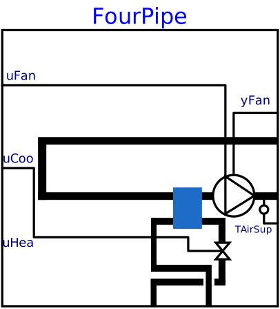
modelFourPipe
System model for a four-pipe fan coil unit
Information
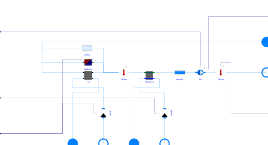
This is a four-pipe fan coil unit system model. The system consists of the following components:
-
A supply fan
fanof class Buildings.Fluid.Movers.FlowControlled_m_flow. -
Heating coil options for no heating coil, a hot-water heating coil or an electric
heating coil determined by the user selection for parameter
heaCoiTypas follows:-
No heating coil with bypass connector
pipBypof class Buildings.Fluid.FixedResistances.PressureDrop ifheaCoiTypis set toBuildings.Controls.OBC.ASHRAE.G36.Types.HeatingCoil.None. -
A hot-water heating coil
heaCoiHWof class Buildings.Fluid.HeatExchangers.DryCoilCounterFlow ifheaCoiTypis set toBuildings.Controls.OBC.ASHRAE.G36.Types.HeatingCoil.WaterBased. -
An electric heating coil
heaCoiEleof class Buildings.Fluid.HeatExchangers.HeaterCooler_u ifheaCoiTypis set toBuildings.Controls.OBC.ASHRAE.G36.Types.HeatingCoil.Electric.
-
No heating coil with bypass connector
-
A chilled-water cooling coil
cooCoiof class Buildings.Fluid.HeatExchangers.WetCoilCounterFlow.
For examples of how to use the model, refer to Buildings.Examples.FanCoils.FourPipe. The following points are salient when using the model:
- The connected air-loop does not need an additional fan, since the fan in this model generates flow.
- The fluid loop connections for hot-water and chilled-water require an external pressure difference between the inlet and the outlet sufficient to overcome the pressure drop across the two respective coils.
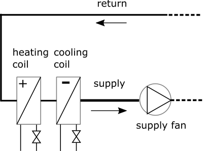
The figure below shows the schematic diagram of the four pipe system when
heaCoiTyp is set to water based using the enumeration
Buildings.Controls.OBC.ASHRAE.G36.Types.HeatingCoil.
Parameters
| Type | Name | Default | Description |
|---|---|---|---|
| System parameters | |||
| Buildings.Controls.OBC.ASHRAE.G36.Types.HeatingCoil | heaCoiTyp | Buildings.Controls.OBC.ASHRAE.G36.Types.HeatingCoil.WaterBased | Heating coil type |
| Modelica.Units.SI.PressureDifference | dpAir_nominal | Total pressure difference across supply and return ports in air loop | |
| Modelica.Units.SI.MassFlowRate | mAir_flow_nominal | Nominal mass flow rate of supply air | |
| Heating coil parameters | |||
| Modelica.Units.SI.HeatFlowRate | QHeaCoi_flow_nominal | Nominal heat flow rate of heating coil | |
| Modelica.Units.SI.Temperature | THeaCoiWatSup_nominal | 333.15 | Design water temperature entering heating coil |
| Modelica.Units.SI.Temperature | THeaCoiAirEnt_nominal | 293.15 | Design air temperature entering heating coil |
| Modelica.Units.SI.MassFlowRate | mHeaCoiWat_flow_nominal | Nominal mass flow rate of heating hot water | |
| Modelica.Units.SI.PressureDifference | dpHeaCoiWat_nominal | Total pressure difference across heating coil (water side) | |
| Modelica.Units.SI.PressureDifference | dpHeaCoiVal_nominal | dpHeaCoiWat_nominal | Design pressure drop of heating water valve |
| Cooling coil parameters | |||
| Modelica.Units.SI.HeatFlowRate | QCooCoi_flow_nominal | Nominal heat flow rate of cooling coil | |
| Modelica.Units.SI.Temperature | TCooCoiWatEnt_nominal | 279.83 | Design water inlet temperature of cooling coil |
| Modelica.Units.SI.Temperature | TCooCoiAirEnt_nominal | 296.15 | Design air inlet temperature of cooling coil |
| Modelica.Units.SI.MassFraction | wCooCoiAirEnt_nominal | 0.012 | Design humidity ratio of inlet air of cooling coil (in kg/kg dry air) |
| Modelica.Units.SI.MassFlowRate | mCooCoiWat_flow_nominal | Nominal mass flow rate of chilled water | |
| Modelica.Units.SI.PressureDifference | dpCooCoiWat_nominal | Total pressure difference across cooling coil (water side) | |
| Modelica.Units.SI.PressureDifference | dpCooCoiVal_nominal | dpCooCoiWat_nominal | Design pressure drop of chilled water valve |
Connectors
| Type | Name | Default | Description |
|---|---|---|---|
| Buildings.Controls.OBC.CDL.Interfaces.RealInput | uHea | Heating loop control signal | |
| Buildings.Controls.OBC.CDL.Interfaces.RealInput | uCoo | Cooling loop control signal | |
| Buildings.Controls.OBC.CDL.Interfaces.RealInput | uFan | Fan normalized speed control signal | |
| Buildings.Controls.OBC.CDL.Interfaces.RealOutput | yFan_actual | Normalized actual fan speed signal | |
| Buildings.Controls.OBC.CDL.Interfaces.RealOutput | TAirSup | Measured supply air temperature | |
| Modelica.Fluid.Interfaces.FluidPort_a | port_air_a | Return air port from zone | |
| Modelica.Fluid.Interfaces.FluidPort_b | port_air_b | Supply air port to the zone | |
| Modelica.Fluid.Interfaces.FluidPort_a | port_CHW_a | Chilled water supply port | |
| Modelica.Fluid.Interfaces.FluidPort_b | port_CHW_b | Chilled water return port | |
| Modelica.Fluid.Interfaces.FluidPort_a | port_HW_a | Hot water supply port | |
| Modelica.Fluid.Interfaces.FluidPort_b | port_HW_b | Hot water return port |
Components
| Type | Name | Default | Description |
|---|---|---|---|
| Buildings.Fluid.Sensors.TemperatureTwoPort | TAirHea | Heating coil discharge air temperature sensor | |
| Buildings.Fluid.HeatExchangers.DryCoilEffectivenessNTU | hex | Hot water heating coil | |
| Buildings.Fluid.Actuators.Valves.TwoWayLinear | valHW | Hot water flow control valve | |
| Buildings.Fluid.HeatExchangers.WetCoilEffectivenessNTU | hexWetNtu | Chilled-water cooling coil | |
| Buildings.Fluid.Actuators.Valves.TwoWayLinear | valCHW | Chilled-water flow control valve | |
| Buildings.Fluid.Sensors.TemperatureTwoPort | TAirLvg | Supply air temperature sensor | |
| Buildings.Fluid.Movers.Preconfigured.SpeedControlled_y | fan | Supply fan | |
| Buildings.Fluid.FixedResistances.PressureDrop | totResAir | Total resistance of air path | |
| Buildings.Fluid.HeatExchangers.HeaterCooler_u | heaCoiEle | Electric heating coil |
Contents
| Name | Description |
|---|---|
 MediumA MediumA | Medium for air |
| MediumHW | Medium for hot water |
| MediumCHW | Medium for chilled water |
Revisions
-
September 22, 2025, by Michael Wetter:
Exposed parameters, reviewed model for first release.
This is for issue 2885. -
August 03, 2022 by Karthik Devaprasad, Sen Huang:
First implementation.