
modelX3BWithRadiantFloor
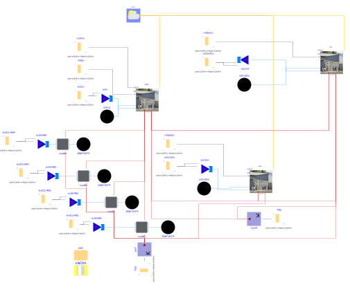
Example model showing a use of X3B
Extends from Modelica.Icons.Example (Icon for runnable examples).
Information
This model demonstrates one potential simulation using the models available in Buildings.ThermalZones.Detailed.FLEXLAB.Rooms.X3B. This model is nearly identical to Buildings.ThermalZones.Detailed.FLEXLAB.Rooms.Examples.X3AWithRadiantFloor. For a description of most of the connections and reasons behind them see that documentation. The changes to make this example model are:
- The room models were changed from X3A models to X3B models.
- Buildings.ThermalZones.Detailed.FLEXLAB.Rooms.X3B.TestCell has one external wall (modeled in datConExt) which was a dividing wall (modeled in datConBou) in Buildings.ThermalZones.Detailed.FLEXLAB.Rooms.X3A.TestCell. Because of this, a few construction indexes changed. Connections were made according to the table in Buildings.ThermalZones.Detailed.FLEXLAB.Rooms.X3B.
Parameters
| Type | Name | Default | Description |
|---|---|---|---|
| Buildings.HeatTransfer.Data.OpaqueConstructions.Generic | slaCon | Construction of the slab | |
| Buildings.Fluid.Data.Pipes.PEX_RADTEST | pipe |
Components
| Type | Name | Default | Description |
|---|---|---|---|
| Buildings.ThermalZones.Detailed.FLEXLAB.Rooms.X3B.TestCell | X3B | ||
| Modelica.Blocks.Sources.CombiTimeTable | intGai | Internal gain heat flow (Radiant = 1, Convective = 2, Latent = 3) | |
| Modelica.Blocks.Sources.CombiTimeTable | shaPos | Position of the shade | |
| Modelica.Blocks.Sources.CombiTimeTable | airCon | Inlet air conditions (y[1] = m_flow, y[2] = T) | |
| Buildings.Fluid.Sources.MassFlowSource_T | airIn | Inlet air conditions (from AHU) for X3A | |
| Buildings.Fluid.Sources.Boundary_pT | airOut | Air outlet for X3A | |
| Buildings.HeatTransfer.Sources.PrescribedTemperature | preT | Temperature of the ground | |
| Modelica.Blocks.Sources.CombiTimeTable | TGro | ||
| Buildings.BoundaryConditions.WeatherData.ReaderTMY3 | weaDat | ||
| Buildings.HeatTransfer.Sources.PrescribedTemperature | preT2 | ||
| Buildings.ThermalZones.Detailed.FLEXLAB.Rooms.X3B.Electrical | ele | Model of the electrical room | |
| Buildings.ThermalZones.Detailed.FLEXLAB.Rooms.X3B.Closet | clo | Model of the closet | |
| Modelica.Blocks.Sources.CombiTimeTable | TNei | Temperature of the neighboring test cell (y[1] = X3A) | |
| Modelica.Blocks.Sources.CombiTimeTable | intGaiEle | Internal gain heat flow for the electrical room | |
| Modelica.Blocks.Sources.CombiTimeTable | airConEle | Inlet air conditions for the connected electrical room (y[1] = m_flow, y[2] = T) | |
| Modelica.Blocks.Sources.CombiTimeTable | airConClo | Inlet air conditions for the connected closet (y[1] = m_flow, y[2] = T) | |
| Buildings.Fluid.Sources.MassFlowSource_T | airInEle | Inlet air conditions (from AHU) for the electrical room | |
| Buildings.Fluid.Sources.Boundary_pT | airOutEle | Air outlet from the electrical room | |
| Buildings.Fluid.Sources.MassFlowSource_T | airInClo | Inlet air conditions (from AHU) for the closet | |
| Buildings.Fluid.Sources.Boundary_pT | airOutClo | Air outlet from the closet | |
| Modelica.Blocks.Sources.CombiTimeTable | intGaiClo | Internal gain heat flow for the closet | |
| Modelica.Blocks.Sources.CombiTimeTable | watCon4B2 | Inlet water conditions (y[1] = m_flow, y[2] = T) | |
| Modelica.Blocks.Sources.CombiTimeTable | watCon4B3 | Inlet water conditions (y[1] = m_flow, y[2] = T) | |
| Buildings.Fluid.Sources.MassFlowSource_T | watIn4B3 | Inlet water conditions (from central plant) | |
| Modelica.Blocks.Sources.CombiTimeTable | watCon4B4 | Inlet water conditions (y[1] = m_flow, y[2] = T) | |
| Buildings.Fluid.Sources.MassFlowSource_T | watIn4B4 | Inlet water conditions (from central plant) | |
| Buildings.Fluid.HeatExchangers.RadiantSlabs.SingleCircuitSlab | sla4B4 | Radiant slab serving the south section of cell X3B. Name is taken from drawing M3.02 | |
| Buildings.Fluid.Sources.Boundary_pT | watOut4B4 | Water outlet | |
| Buildings.Fluid.HeatExchangers.RadiantSlabs.SingleCircuitSlab | sla4B3 | Radiant slab serving the south-central section of cell X3B. Name is taken from drawing M3.02 | |
| Buildings.Fluid.Sources.Boundary_pT | watOut4B3 | Water outlet | |
| Buildings.Fluid.Sources.MassFlowSource_T | watIn4B2 | Inlet water conditions (from central plant) | |
| Buildings.Fluid.HeatExchangers.RadiantSlabs.SingleCircuitSlab | sla4B2 | Radiant slab serving the north-central section of cell X3B. Name is taken from drawing M3.02 | |
| Buildings.Fluid.Sources.Boundary_pT | watOut4B2 | Water outlet | |
| Modelica.Blocks.Sources.CombiTimeTable | watCon4B1 | Inlet water conditions (y[1] = m_flow, y[2] = T) | |
| Buildings.Fluid.Sources.MassFlowSource_T | watIn4B1 | Inlet water conditions (from central plant) | |
| Buildings.Fluid.HeatExchangers.RadiantSlabs.SingleCircuitSlab | sla4B1 | Radiant slab serving the north side of cell X3B. Name is taken from drawing M3.02 | |
| Buildings.Fluid.Sources.Boundary_pT | watOut4B1 | Water outlet |
Contents
| Name | Description |
|---|---|
 Air Air | Air model used in the example model |
 Water Water | Water model used in the radiant slab loop |
Revisions
-
December 07, 2016, by Thierry S. Nouidui:
Changed example to place a state at the surface. -
August 23, 2016, by Thierry S. Nouidui:
Corrected the syntax of the weather data file name entry. -
April 21, 2016, by Michael Wetter:
ReplacedModelicaServices.ExternalReferences.loadResourcewithModelica.Utilities.Files.loadResource. -
December 22, 2014 by Michael Wetter:
RemovedModelica.Fluid.Systemto address issue #311. - September 2, 2014, by Michael Wetter:
Corrected wrong pipe diameter. - June 30, 2014, by Michael Wetter:
Specified equations to be used to compute the initial conditions. - October 11, 2013, by Michael Wetter:
Added missingparameterkeyword in the declaration of the data record. - Sep 18, 2013 by Peter Grant:
First implementation.