
modelTestStandSegmented
Simulate the fuel cell with multiple segments in the y direction
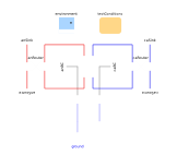
Extends from TestStand (Simulate the fuel cell under prescribed conditions).
Parameters
| Type | Name | Default | Description |
|---|---|---|---|
| Geometry | |||
| Integer | n_y | 6 | Number of segments in the y direction |
Components
| Type | Name | Default | Description |
|---|---|---|---|
| Q.Current | zI (from TestStand) | Electrical current | |
| Q.Potential | w (from TestStand) | load.v*U.V | Potential |
| Q.CurrentAreic | J (from TestStand) | zI/cell.caFP.A[Axis.x] | Current density |
| Q.Number | J_Apercm2 (from TestStand) | J*U.cm^2/U.A | Current density, in A/cm2 |
| Q.PressureAbsolute | p_an_in (from TestStand) | average(average(anSource.gas.H2.boundary.p + anSource.gas.H2O.boundary.p)) | Total pressure at the anode inlet |
| Q.PressureAbsolute | p_ca_in (from TestStand) | average(average(caSource.gas.H2O.boundary.p + p_N2_in + caSource.gas.O2.boundary.p)) | Total pressure at the cathode inlet |
| Q.Pressure | Deltap_an (from TestStand) | environment.p - p_an_in | Pressure difference down the anode channel |
| Q.Pressure | Deltap_ca (from TestStand) | environment.p - p_ca_in | Pressure difference down the cathode channel |
| Q.Potential | Deltaw_O2 (from TestStand) | (DataO2.g(caSource[1, 1].gas.O2.boundary.T, caSource[1, 1].gas.O2.boundary.p) - cell.caCL.subregions[1, 1, 1].gas.O2.g)/4 | Voltage loss due to O2 supply |
| Q.Potential | Deltaw_H2O (from TestStand) | (DataH2O.g(caSource[1, 1].gas.H2O.boundary.T, caSource[1, 1].gas.H2O.boundary.p) - cell.caCL.subregions[1, 1, 1].gas.H2O.g)/2 | Voltage loss due to H2O removal |
| Q.Potential | Deltaw_H2 (from TestStand) | (DataH2.g(anSource[1, 1].gas.H2.boundary.T, anSource[1, 1].gas.H2.boundary.p) - cell.anCL.subregions[1, 1, 1].gas.H2.g)/2 | Voltage loss due to H2 supply |
| Q.Potential | 'Deltaw_e-' (from TestStand) | cell.caFP.subregions[1, 1, 1].graphite.'e-'.g_boundaries[1, Side.p] - cell.caCL.subregions[1, 1, 1].graphite.'e-'.g + cell.anCL.subregions[1, 1, 1].graphite.'e-'.g - cell.anFP.subregions[1, 1, 1].graphite.'e-'.g_boundaries[1, Side.n] | Voltage loss due to e- transport |
| Q.Potential | 'Deltaw_H+' (from TestStand) | cell.anCL.subregions[1, 1, 1].ionomer.'H+'.g - cell.caCL.subregions[1, 1, 1].ionomer.'H+'.g | Voltage loss due to H+ transport |
| Q.Potential | Deltaw_an (from TestStand) | cell.anCL.subregions[1, 1, 1].graphite.'e-Transfer'.Deltag | Anode overpotential |
| Q.Potential | Deltaw_ca (from TestStand) | -cell.caCL.subregions[1, 1, 1].graphite.'e-Transfer'.Deltag | Cathode overpotential |
| Cell | cell (from TestStand) | ||
| Conditions.ByConnector.BoundaryBus.Single.Sink[cell.n_y,cell.n_z] | anBC (from TestStand) | Boundary condition for the anode end plate, except electrical | |
| Conditions.ByConnector.BoundaryBus.Single.Source[cell.anFP.n_x,cell.n_z] | anSource (from TestStand) | Source for the anode reactant stream | |
| Conditions.ByConnector.BoundaryBus.Single.Sink[cell.anFP.n_x,cell.n_z] | anSink (from TestStand) | Sink for the anode reactant stream | |
| Conditions.ByConnector.BoundaryBus.Single.Source[cell.n_y,cell.n_z] | caBC (from TestStand) | Boundary condition for the cathode end plate, except electrical | |
| Conditions.ByConnector.BoundaryBus.Single.Source[cell.caFP.n_x,cell.n_z] | caSource (from TestStand) | Source for the cathode reactant stream | |
| Conditions.ByConnector.BoundaryBus.Single.Sink[cell.caFP.n_x,cell.n_z] | caSink (from TestStand) | Sink for the cathode reactant stream | |
| Conditions.Environment | environment (from TestStand) | Environmental conditions | |
| Modelica.Electrical.Analog.Sources.RampCurrent | load (from TestStand) | ||
| Modelica.Electrical.Analog.Basic.Ground | ground (from TestStand) | ||
| Conditions.Adapters.MSL.Electronic | anAdapt (from TestStand) | Interface with Modelica.Electrical on the anode side | |
| Conditions.Adapters.MSL.Electronic | caAdapt (from TestStand) | Interface with Modelica.Electrical on the cathode side | |
| Conditions.Router[cell.anFP.n_x,cell.n_z] | anRouter (from TestStand) | Switch to route the anode for reverse flow | |
| Conditions.Router[cell.anFP.n_x,cell.n_z] | caRouter (from TestStand) | Switch to route the cathode for reverse flow | |
| TestConditions | testConditions (from TestStand) | Test conditions |