
modelLineForceWithTwoMasses
Extends from Modelica.Icons.Example (Icon for runnable examples).
Information
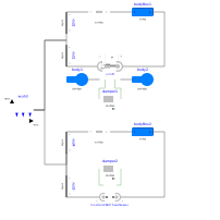
It is demonstrated how to implement line force components that shall have mass properties. Two alternative implementations are given:
- With JointUPS:
Modelica.Mechanics.MultiBody.Joints.Assemblies.JointUPS is an aggregation of a universal, a prismatic and a spherical joint that approximates a real force component, such as a hydraulic cylinder. At the two frames of the prismatic joint (frame_ia, frame_ib of jointUPS) two bodies are attached. The parameters are selected such that the center of masses of the two bodies are located on the line connecting frame_a and frame_b of the jointUPS component. Both bodies have the same mass and the inertia tensor is set to zero, i.e., the two bodies are treated as point masses. - With LineForceWithTwoMasses:
Modelica.Mechanics.MultiBody.Forces.LineForceWithTwoMasses is a line force component with the built-in property that two point masses are located on the line on which the line force is acting. The parameters are selected in such a way that the same system as with the jointUPS component is described.
In both cases, a linear 1-dimensional translational damper from the Modelica.Mechanics.Translational library is used as line force between the two attachment points. Simulate this system and plot the differences of the cut forces at both sides of the line force component ("rod_f_diff" and "body_f_diff"). Both vectors should be zero (depending on the chosen relative tolerance of the integration, the difference is in the order of 1e-10 … 1e-15).
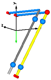
Note, that the implementation with the LineForceWithTwoMasses component is simpler and more convenient. An animation of this simulation is shown in the figure below. The system on the left side in the front is the animation with the LineForceWithTwoMasses component whereas the system on the right side in the back is the animation with the JointUPS component.
Parameters
| Type | Name | Default | Description |
|---|---|---|---|
| SI.Mass | m | 1 | Mass of point masses |