The 3 signals of the force connector are interpreted as the x-, y- and z-coordinates of a force acting at the frame connector to which frame_b of this component is attached. Via parameter resolveInFrame it is defined, in which frame these coordinates shall be resolved:
| Types.ResolveInFrameAB. | Meaning |
|---|---|
| world | Resolve input force in world frame |
| frame_a | Resolve input force in frame_a |
| frame_b | Resolve input force in frame_b (= default) |
| frame_resolve | Resolve input force in frame_resolve (frame_resolve must be connected) |
If resolveInFrame = ResolveInFrameAB.frame_resolve, the force coordinates are with respect to the frame, that is connected to frame_resolve.
If force={100,0,0}, and for all parameters the default setting is used, then the interpretation is that a force of 100 N is acting along the positive x-axis of frame_b.
Note, the cut-torque in frame_b (frame_b.t) is always set to zero. Additionally, a force and torque acts on frame_a in such a way that the force and torque balance between frame_a and frame_b is fulfilled.
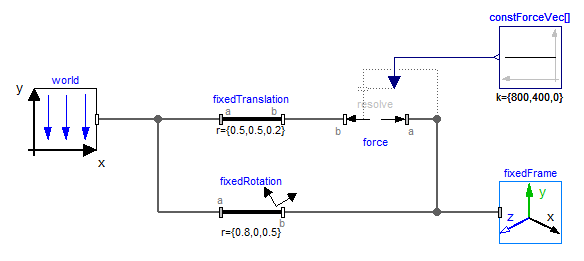
An example how to use this model is given in the following figure:
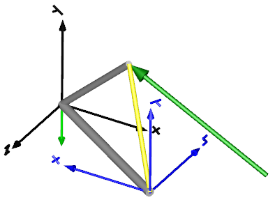
This leads to the following animation (the yellow cylinder characterizes the line between frame_a and frame_b of the Force component, i.e., the force acts with negative sign also on the opposite side of this cylinder, but for clarity this is not shown in the animation):