The 3 signals of the force and torque connector are interpreted as the x-, y- and z-coordinates of a force and torque acting at the frame connector to which frame_b of this component is attached. Via parameter resolveInFrame it is defined, in which frame these coordinates shall be resolved:
| Types.ResolveInFrameB. | Meaning |
|---|---|
| world | Resolve input force and torque in world frame (= default) |
| frame_b | Resolve input force and torque in frame_b |
| frame_resolve | Resolve input force and torque in frame_resolve (frame_resolve must be connected) |
If resolveInFrame = Types.ResolveInFrameB.frame_resolve, the force and torque coordinates are with respect to the frame, that is connected to frame_resolve.
If force={100,0,0}, and for all parameters the default setting is used, then the interpretation is that a force of 100 N is acting along the positive x-axis of frame_b.
Conceptually, a force and torque acts on the world frame in such a way that the force and torque balance between world.frame_b and frame_b is fulfilled. For efficiency reasons, this reaction torque is, however, not computed.
The force and torque are by default visualized as an arrow (force) and as a double arrow (torque) acting at the connector to which they are connected. The colors of the arrows can be defined via forceColor and torqueColor. The arrows point in the directions defined by the force and torque vectors. The lengths of the arrows are proportional to the length of the force and torque vectors, respectively, using tool-dependent scaling factors.
An example how to use this model is given in the following figure:
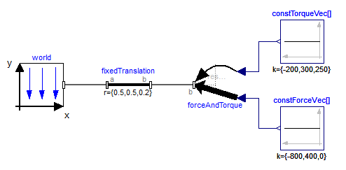
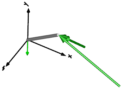
This leads to the following animation