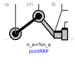
modelJointRRP
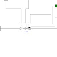
Extends from Interfaces.PartialTwoFramesDoubleSize (Base model for components providing two frame connectors + outer world + assert to guarantee that the component is connected (default icon size is factor 2 larger as usual)).
Information
This component consists of 2 revolute joints with parallel axes of rotation that and a prismatic joint with a translational axis that is orthogonal to the revolute joint axes, see the default animation in the following figure (the axes vectors are not part of the default animation):
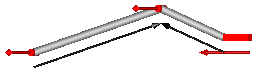
This joint aggregation introduces neither constraints nor state variables and should therefore be used in kinematic loops whenever possible to avoid non-linear systems of equations. It is only meaningful to use this component in planar loops. Basically, the position and orientation of the 3 joints as well as of frame_ia, frame_ib, and frame_im are calculated by solving analytically a non-linear equation, given the position and orientation at frame_a and at frame_b.
Connector frame_a is the "left" side of the first revolute joint whereas frame_ia is the "right side of this revolute joint, fixed in rod 1. Connector frame_b is the "right" side of the prismatic joint whereas frame_ib is the "left" side of this prismatic joint, fixed in rod 2. Finally, connector frame_im is the connector at the "right" side of the revolute joint in the middle, fixed in rod 2. The frames frame_b, frame_ib, frame_im are always parallel to each other.
The easiest way to define the parameters of this joint is by moving the MultiBody system in a reference configuration where all frames of all components are parallel to each other (alternatively, at least frame_a, frame_ia, frame_im, frame_ib, frame_b of the JointRRP joint should be parallel to each other when defining an instance of this component).
Basically, the JointRRP model consists internally of a universal - spherical - prismatic joint aggregation (= JointUSP). In a planar loop this will behave as if 2 revolute joints with parallel axes and 1 prismatic joint are connected by rigid rods.
Parameters
| Type | Name | Default | Description |
|---|---|---|---|
| Boolean | animation | true | = true, if animation shall be enabled |
| Modelica.Mechanics.MultiBody.Types.Axis | n_a | {0, 0, 1} | Axes of the two revolute joints resolved in frame_a (both axes are parallel to each other) |
| Modelica.Mechanics.MultiBody.Types.Axis | n_b | {-1, 0, 0} | Axis of prismatic joint fixed and resolved in frame_b (must be orthogonal to revolute joint axes) |
| SI.Position[3] | rRod1_ia | {1, 0, 0} | Vector from origin of frame_a to revolute joint in the middle, resolved in frame_ia |
| SI.Position[3] | rRod2_ib | {-1, 0, 0} | Vector from origin of frame_ib to revolute joint in the middle, resolved in frame_ib (frame_ib is parallel to frame_b) |
| SI.Position | s_offset | 0 | Relative distance offset of prismatic joint (distance between the prismatic joint frames = s(t) + s_offset) |
| SI.Position | s_guess | 0 | Select the configuration such that at initial time |s(t0)-s_guess| is minimal |
| Real[3] | e_a | Modelica.Math.Vectors.normalizeWithAssert(n_a) | Unit vector along axes of rotations, resolved in frame_a |
| Real[3] | e_ia | jointUSP.e2_ia | Unit vector along axes of rotations, resolved in frame_ia |
| Real[3] | e_im | Unit vector along axes of rotations, resolved in frame_im | |
| Real[3] | e_b | jointUSP.prismatic.e | Unit vector along axes of translation of the prismatic joint, resolved in frame_b and frame_ib |
| Animation › if animation = true | |||
| SI.Distance | cylinderLength | world.defaultJointLength | Length of cylinders representing the revolute joints |
| SI.Distance | cylinderDiameter | world.defaultJointWidth | Diameter of cylinders representing the revolute joints |
| Types.Axis | boxWidthDirection | {0, 1, 0} | Vector in width direction of prismatic joint, resolved in frame_b |
| SI.Distance | boxWidth | world.defaultJointWidth | Width of prismatic joint box |
| SI.Distance | boxHeight | boxWidth | Height of prismatic joint box |
| SI.Diameter | rodDiameter | 1.1*cylinderDiameter | Diameter of the two rods connecting the joints |
| Advanced | |||
| Boolean | checkTotalPower | false | = true, if total power flowing into this component shall be determined (must be zero) |
Connectors
| Type | Name | Default | Description |
|---|---|---|---|
| Interfaces.Frame_a | frame_a (from PartialTwoFramesDoubleSize) | Coordinate system fixed to the component with one cut-force and cut-torque | |
| Interfaces.Frame_b | frame_b (from PartialTwoFramesDoubleSize) | Coordinate system fixed to the component with one cut-force and cut-torque | |
| Modelica.Mechanics.MultiBody.Interfaces.Frame_a | frame_ia | Coordinate system at origin of frame_a fixed at connecting rod of revolute joints | |
| Modelica.Mechanics.MultiBody.Interfaces.Frame_b | frame_ib | Coordinate system at origin of frame_b fixed at connecting rod of revolute and prismatic joint | |
| Modelica.Mechanics.MultiBody.Interfaces.Frame_b | frame_im | Coordinate system at origin of revolute joint in the middle fixed at connecting rod of revolute and prismatic joint | |
| Modelica.Mechanics.Translational.Interfaces.Flange_a | axis | 1-dim. translational flange that drives the prismatic joint | |
| Modelica.Mechanics.Translational.Interfaces.Flange_b | bearing | 1-dim. translational flange of the drive bearing of the prismatic joint |
Components
| Type | Name | Default | Description |
|---|---|---|---|
| Types.Color | cylinderColor | Modelica.Mechanics.MultiBody.Types.Defaults.JointColor | Color of cylinders representing the revolute joints |
| Types.Color | boxColor | cylinderColor | Color of prismatic joint box |
| Types.Color | rodColor | Modelica.Mechanics.MultiBody.Types.Defaults.RodColor | Color of the two rods connecting the joints |
| Types.SpecularCoefficient | specularCoefficient | world.defaultSpecularCoefficient | Reflection of ambient light (= 0: light is completely absorbed) |
| SI.Power | totalPower | jointUSP.totalPower | Total power flowing into this element, if checkTotalPower=true (otherwise dummy) |
| JointUSP | jointUSP |