modelRevolute
Information
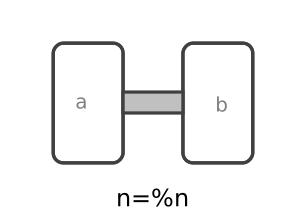
Joint where frame_b rotates around axis n which is fixed in frame_a. The two frames coincide when the rotation angle "phi = 0".
Optionally, two additional 1-dimensional mechanical flanges (flange "axis" represents the driving flange and flange "support" represents the bearing) can be enabled via parameter useAxisFlange. The enabled axis flange can be driven with elements of the Modelica.Mechanics.Rotational library.
In the "Advanced" menu it can be defined via parameter stateSelect that the rotation angle "phi" and its derivative shall be definitely used as states by setting stateSelect=StateSelect.always. Default is StateSelect.prefer to use the joint angle and its derivative as preferred states. The states are usually selected automatically. In certain situations, especially when closed kinematic loops are present, it might be slightly more efficient, when using the StateSelect.always setting.
If a planar loop is present, e.g., consisting of 4 revolute joints where the joint axes are all parallel to each other, then there is no longer a unique mathematical solution and the symbolic algorithms will fail. Usually, an error message will be printed pointing out this situation. In this case, one revolute joint of the loop has to be replaced by a Joints.RevolutePlanarLoopConstraint joint. The effect is that from the 5 constraints of a usual revolute joint, 3 constraints are removed and replaced by appropriate known variables (e.g., the force in the direction of the axis of rotation is treated as known with value equal to zero; for standard revolute joints, this force is an unknown quantity).
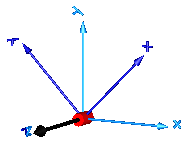
In the following figure the animation of a revolute joint is shown. The light blue coordinate system is frame_a and the dark blue coordinate system is frame_b of the joint. The black arrow is parameter vector "n" defining the translation axis (here: n = {0,0,1}, phi.start = 45o).
Parameters
| Type | Name | Default | Description |
|---|---|---|---|
| Boolean | useAxisFlange | false | = true, if axis flange is enabled |
| Boolean | animation | true | = true, if animation shall be enabled (show axis as cylinder) |
| Modelica.Mechanics.MultiBody.Types.Axis | n | {0, 0, 1} | Axis of rotation resolved in frame_a (= same as in frame_b) |
| Animation › if animation = true | |||
| SI.Distance | cylinderLength | world.defaultJointLength | Length of cylinder representing the joint axis |
| SI.Distance | cylinderDiameter | world.defaultJointWidth | Diameter of cylinder representing the joint axis |
| Advanced | |||
| StateSelect | stateSelect | StateSelect.prefer | Priority to use joint angle phi and w=der(phi) as states |
Connectors
| Type | Name | Default | Description |
|---|---|---|---|
| Modelica.Mechanics.Rotational.Interfaces.Flange_a | axis | 1-dim. rotational flange that drives the joint | |
| Modelica.Mechanics.Rotational.Interfaces.Flange_b | support | 1-dim. rotational flange of the drive support (assumed to be fixed in the world frame, NOT in the joint) | |
| Modelica.Mechanics.MultiBody.Interfaces.Frame_a | frame_a | Coordinate system fixed to the joint with one cut-force and cut-torque | |
| Modelica.Mechanics.MultiBody.Interfaces.Frame_b | frame_b | Coordinate system fixed to the joint with one cut-force and cut-torque |
Components
| Type | Name | Default | Description |
|---|---|---|---|
| Modelica.Mechanics.MultiBody.Types.Color | cylinderColor | Modelica.Mechanics.MultiBody.Types.Defaults.JointColor | Color of cylinder representing the joint axis |
| Modelica.Mechanics.MultiBody.Types.SpecularCoefficient | specularCoefficient | world.defaultSpecularCoefficient | Reflection of ambient light (= 0: light is completely absorbed) |
| SI.Angle | phi | Relative rotation angle from frame_a to frame_b | |
| SI.AngularVelocity | w | First derivative of angle phi (relative angular velocity) | |
| SI.AngularAcceleration | a | Second derivative of angle phi (relative angular acceleration) | |
| SI.Torque | tau | Driving torque in direction of axis of rotation | |
| SI.Angle | angle | = phi |