Let us now proceed to create alternative representations of a generation unit so that we can use them in our experiments.
GenerationUnits package and duplicate
the GeneratorOnly model to
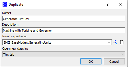
create a new model called GeneratorTurbGov that also has a
turbine/governor block.
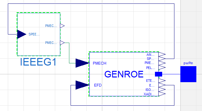
IEEEG1 turbine/governor
block from OpenIPSL.Electrical.Controls.PSSE.TG.
PMECH0 output and the PMECH input of the machine. Be aware
that we now have a turbine block, therefore connect its HP-stage
mechanical power output to the corresponding input of the machine.
Your model should look like this:
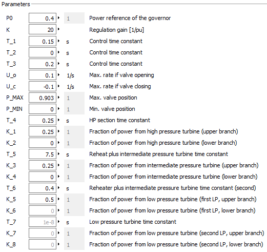
IEEEG1 parameters:
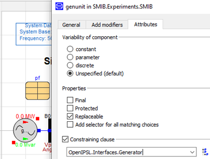
SMIB experiment model and double-click
the genunit component.OpenIPSL.Interfaces.Generator from the
drop-down list.
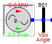
📌 The GenerationUnit icon
should now turn into

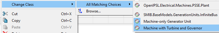
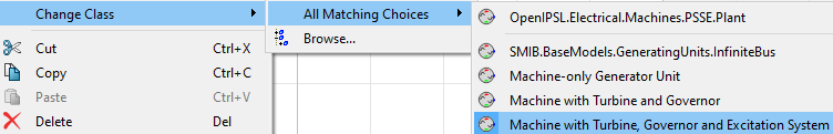
SMIB model and right-click the
genunit block to change the class to the " Machine
with Turbine and Governor" option.
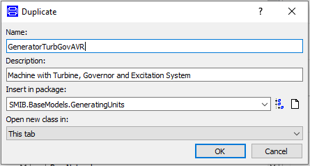
GeneratorTurbGovAVR. For this to be done
make sure you duplicate the GeneratorTurbGov model.
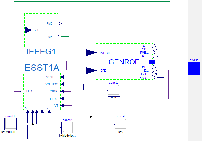
ESST1A
excitation system block from OpenIPSL.Electrical.Controls.PSSE.ES to
the diagram layer of the new model. Add 4 Constant
blocks from Modelica.Blocks.Sources too.
GENROE machine
component, remove the connection between EFD and EFD0. The EFD input of the machine should now be
connected to the respective output from the excitation system.
| GENROE Machine | EEST1A |
|---|---|
|
ETERM |
VT |
|
ETERM |
ECOMP |
|
EFD0 |
EFD0 |
|
XADIFD |
XADIFD |
Constant blocks to set the excitation
system inputs to the values indicated in the following table:
| Input | Value |
|---|---|
|
VOTHSG |
0 |
|
VOTHSG2 |
0 |
|
VUEL |
0 |
|
VOEL |
Modelica.Constants.inf |
|
VUEL2 |
-Modelica.Constants.inf |
|
VUEL3 |
-Modelica.Constants.inf |
Your model should now look like this:
SMIB
experiment model and change the class of the genunit
component so that it now uses the model with the excitation
system.SMIB model when right-clicking the
genunit component, you should now be able to see the new
generation unit model among the options for class change. Update
the component class so that it uses the most recent generation unit
model.
SMIB model
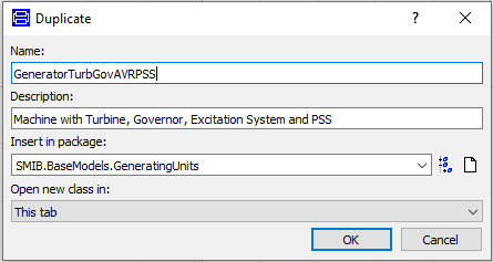
for 10 seconds.GenerationUnitsGeneratorTurbGovAVR. Name the new model
GeneratorTurbGovAVRPSS. This
generation unit model is going to include a power system stabilizer
(PSS).
OpenIPSL.Electrical.Controls.PSSE.PSS
package and locate the PSS2A
model (Dual-Input Stabilizer Model [IEEE1992]).
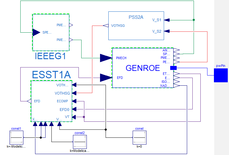
Drag-and-drop an instance to the diagram layer of the new
generation unit model.VOTHSG input of the
excitation system component. Now this input should be connected to
the output of the PSS2A
block.V_S1 and
V_S2 inputs of the
PSS2A block to the
SPEED_HP and PELEC outputs of the machine component,
respectively.
Make sure that your model looks like the figure below:
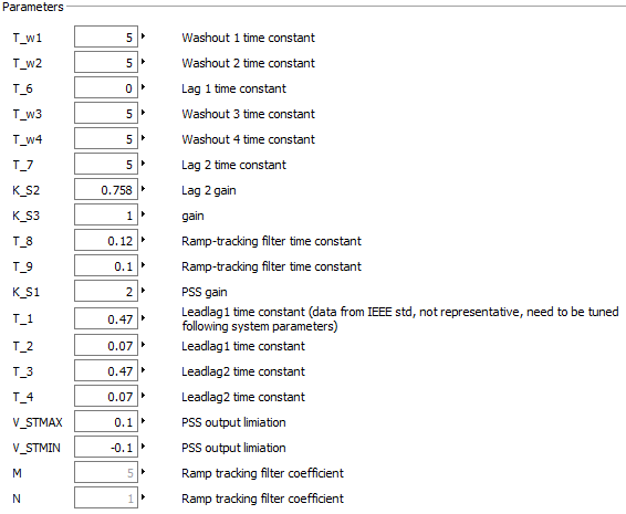
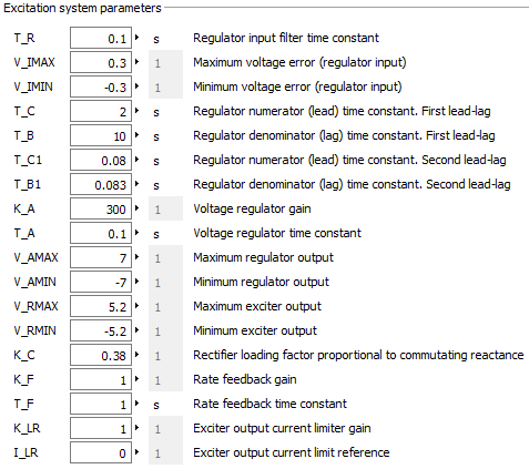
PSS2A
component in order to update the parameters as indicated below: