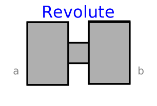
modelRevolute

Extends from PlanarMechanics.Interfaces.PartialTwoFrames (Partial model with two frames).
Information
Joint of in-plane rotation of frame_b relative to frame_a.
The two frames coincide when the rotation angle phi = 0°.
Optionally, two additional one-dimensional mechanical flanges (flange
flange_a represents the driving flange and flange
support represents the bearing) can be enabled via
parameter useFlange. The enabled flange_a
flange can be driven with elements of the
Modelica.Mechanics.Rotational
library.
In the "Initialization" block, angular position phi,
angular velocity w as well as angular
acceleration z can be initialized.
It can be defined via parameter (in "Advanced" tab)
stateSelect that the relative angle phi
and its derivative shall be definitely used as states by setting
stateSelect = StateSelect.always.
In "Animation" group, animation parameters for this model can be set,
where zPosition represents the model's position along
the z axis in 3D animation. Some of the values can be preset
by an outer PlanarWorld
model.
Parameters
| Type | Name | Default | Description |
|---|---|---|---|
| Boolean | useFlange | false | = true, if force flange enabled, otherwise implicitly grounded |
| Boolean | animate | true | = true, if animation shall be enabled |
| Advanced | |||
| StateSelect | stateSelect | StateSelect.default | Priority to use phi and w as states |
| Animation › if animation = true | |||
| SI.Length | zPosition | planarWorld.defaultZPosition | Position z of cylinder representing the joint axis |
| SI.Distance | cylinderLength | planarWorld.defaultJointLength | Length of cylinder representing the joint axis |
| SI.Distance | cylinderDiameter | planarWorld.defaultJointWidth | Diameter of cylinder representing the joint axis |
| Boolean | extraLine | false | Enable black line in the cylinder to show the joint rotation |
Connectors
| Type | Name | Default | Description |
|---|---|---|---|
| Frame_a | frame_a (from PartialTwoFrames) | Coordinate system fixed to the component with one cut-force and cut-torque | |
| Frame_b | frame_b (from PartialTwoFrames) | Coordinate system fixed to the component with one cut-force and cut-torque | |
| Modelica.Mechanics.Rotational.Interfaces.Flange_a | flange_a | ||
| Modelica.Mechanics.Rotational.Interfaces.Flange_b | support | 1-dim. rotational flange of the drive support (assumed to be fixed in the world frame, NOT in the joint) |
Components
| Type | Name | Default | Description |
|---|---|---|---|
| MB.Types.Color | cylinderColor | Types.Defaults.JointColor | Color of cylinder representing the joint axis |
| MB.Types.SpecularCoefficient | specularCoefficient | planarWorld.defaultSpecularCoefficient | Reflection of ambient light (= 0: light is completely absorbed) |
| SI.Angle | phi | Angular position | |
| SI.AngularVelocity | w | Angular velocity | |
| SI.AngularAcceleration | z | Angular acceleration | |
| SI.Torque | t | Torque | |
| MB.Visualizers.Advanced.Shape | cylinder |
Revisions
 Developed 2010 at the DLR Institute of System Dynamics and Control