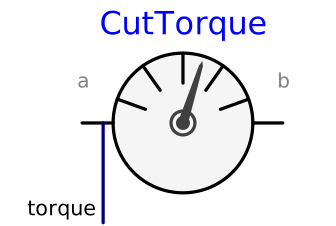
modelCutTorque
Measure cut torque
Extends from Internal.PartialCutTorqueSensor (Base model to measure the cut force and/or torque between two frames, defined by components).
Information
The cut-torque acting between the two frames to which this model
is connected, is determined and provided at the output signal
connector torque (= frame_a.t).
If parameter positiveSign = false, the negative
cut-torque is provided (= frame_b.t).
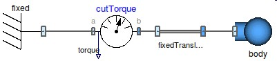
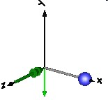
In the following figure the modeling and animation of this sensor is shown.
Parameters
| Type | Name | Default | Description |
|---|---|---|---|
| Boolean | animation | true | = true, if animation shall be enabled (show arrow) |
| Boolean | positiveSign | true | = true, if torque with positive sign is returned (= frame_a.t), otherwise with negative sign (= frame_b.t) |
Connectors
| Type | Name | Default | Description |
|---|---|---|---|
| Interfaces.Frame_a | frame_a (from PartialCutTorqueSensor) | Coordinate system a | |
| Interfaces.Frame_b | frame_b (from PartialCutTorqueSensor) | Coordinate system b | |
| Modelica.Blocks.Interfaces.RealOutput | torque | Cut torque resolved in frame defined by resolveInFrame |
Components
| Type | Name | Default | Description |
|---|---|---|---|
| Real | Nm_to_m | planarWorld.defaultNm_to_m | Torque arrow scaling (length = torque/Nm_to_m) |
| SI.Diameter | torqueDiameter | planarWorld.defaultArrowDiameter | Has no longer an effect and is only kept for backwards compatibility (arrow visualization by Vector now) |
| MB.Types.Color | torqueColor | PlanarMechanics.Types.Defaults.TorqueColor | Color of torque arrow |
| MB.Types.SpecularCoefficient | specularCoefficient | planarWorld.defaultSpecularCoefficient | Reflection of ambient light (= 0: light is completely absorbed) |
Revisions
 Developed 2010 at the DLR Institute of System Dynamics and Control