modelPR
PR Mechanism
Extends from Servomechanisms.Utilities.IconNameB.
Information
General
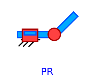
This class models a PR mechanism.
Implementation
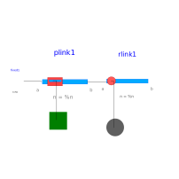
It uses RLink and PLink elements.

Notes
- The first joint is fixed in the origin.
-
By default the revolute joint axis is the z axis (rotation axis in direction
n=[0,0,1]
), the prismatic joint axis is the x axisn=[1,0,0]
and gravity is in directionn=[0,-1,0]
- The generalized coordinates theta and d are the angle in radians and distance in meters respectively.
- The interfaces are Modelica.Mechanics.Rotational and Modelica.Mechanics.Translational
- The mechanical parameters of each link are editable (dimensions, mass, etc)
Example
Parameters
| Type | Name | Default | Description |
|---|---|---|---|
| String | shape1 | "box" | shape of visualizer:"shape", "box", "cylinder" |
| Modelica.Mechanics.MultiBody.Types.Axis | n1 | {1, 0, 0} | Axis of rotation resolved in frame_a (= same as in frame_b) |
| String | shape2 | "box" | shape of visualizer:"shape", "box", "cylinder" |
| Modelica.Mechanics.MultiBody.Types.Axis | n2 | {0, 0, 1} | Axis of rotation resolved in frame_a (= same as in frame_b) |
| SI.Acceleration | g | 9.81 | Constant gravity acceleration |
| if shape | |||
| SI.Position[3] | r1 | Vector from frame_a to frame_b resolved in frame_a | |
| SI.Position[3] | r_CM1 | Vector from frame_a to center of mass, resolved in frame_a | |
| SI.Mass | m1 | Mass of rigid body | |
| SI.Length | shapeLength1 | 1 | |
| SI.Distance | shapeWidth1 | boxLength1/20 | |
| SI.Distance | shapeHeight1 | boxWidth1 | |
| String | shapeType1 | "modelica://Servomechanisms//Resources//b2.dxf" | Type of shape |
| Real | extra1 | 1 | Additional parameter depending on shapeType (see docu of Visualizers.Advanced.Shape) |
| SI.Position[3] | r2 | Vector from frame_a to frame_b resolved in frame_a | |
| SI.Position[3] | r_CM2 | Vector from frame_a to center of mass, resolved in frame_a | |
| SI.Mass | m2 | Mass of rigid body | |
| SI.Length | shapeLength2 | 1 | |
| SI.Distance | shapeWidth2 | boxLength2/20 | |
| SI.Distance | shapeHeight2 | boxWidth2 | |
| String | shapeType2 | "modelica://Servomechanisms//Resources//b2.dxf" | Type of shape |
| Real | extra2 | 1 | Additional parameter depending on shapeType (see docu of Visualizers.Advanced.Shape) |
| if shape › Inertia tensor (resolved in center of mass, parallel to frame_a) | |||
| SI.Inertia | I_111 | 0.001 | (1,1) element of inertia tensor |
| SI.Inertia | I_221 | 0.001 | (2,2) element of inertia tensor |
| SI.Inertia | I_331 | 0.001 | (3,3) element of inertia tensor |
| SI.Inertia | I_211 | 0 | (2,1) element of inertia tensor |
| SI.Inertia | I_311 | 0 | (3,1) element of inertia tensor |
| SI.Inertia | I_321 | 0 | (3,2) element of inertia tensor |
| SI.Inertia | I_112 | 0.001 | (1,1) element of inertia tensor |
| SI.Inertia | I_222 | 0.001 | (2,2) element of inertia tensor |
| SI.Inertia | I_332 | 0.001 | (3,3) element of inertia tensor |
| SI.Inertia | I_212 | 0 | (2,1) element of inertia tensor |
| SI.Inertia | I_312 | 0 | (3,1) element of inertia tensor |
| SI.Inertia | I_322 | 0 | (3,2) element of inertia tensor |
| if box | |||
| SI.Length | boxLength1 | 1 | |
| SI.Distance | boxWidth1 | boxLength1/20 | |
| SI.Distance | boxHeight1 | boxWidth1 | |
| SI.Length | boxLength2 | 1 | |
| SI.Distance | boxWidth2 | boxLength2/20 | |
| SI.Distance | boxHeight2 | boxWidth2 | |
| if cylinder | |||
| SI.Length | cylinderLength1 | 1 | |
| SI.Distance | cylinderDiameter1 | cylinderLength1/20 | |
| SI.Length | cylinderLength2 | 1 | |
| SI.Distance | cylinderDiameter2 | cylinderLength2/20 | |
| Parameters only for cylinder and box | |||
| SI.Density | density1 | 7700 | Density of link (e.g., steel: 7700 .. 7900, wood : 400 .. 800) |
| SI.Density | density2 | 7700 | Density of link (e.g., steel: 7700 .. 7900, wood : 400 .. 800) |
Connectors
| Type | Name | Default | Description |
|---|---|---|---|
| Modelica.Mechanics.Rotational.Interfaces.Flange_a | flange_r2 | ||
| Modelica.Mechanics.Translational.Interfaces.Flange_a | flange_p1 |
Components
| Type | Name | Default | Description |
|---|---|---|---|
| Modelica.Mechanics.MultiBody.Parts.Fixed | fixed1 | ||
| Servomechanisms.Mechanism.PLink | plink1 | ||
| Servomechanisms.Mechanism.RLink | rlink1 |