modelElectricThermalEnergyStorage

Information

1. Purpose of model

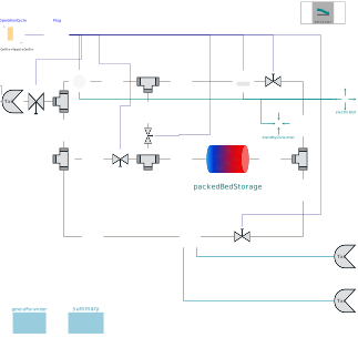
The model determines the efficiency of a Electric Thermal Energy Storage System, accounting for self discharge via heat losses to the environment, thermal destratification in the packed bed and fan work. In an Electric Thermal Energy Storage, energy is stored as thermal energy in a horizontal-flow packed bed of natural rocks. At the charge process, a fan moves air through a resistance heater. The air then flows through the packed bed pores and heats the storage material. The thermal gradient or thermocline inside the packed bed moves in air flow direction at a lower speed. At discharge, the fan moves air through the storage in reverse direction. The air heated from the packed bed is used to produce steam in a heat recovery steam generator.

See the references for more information.

2. Level of detail, physical effects considered, and physical insight

It has to be noted, that this model does not include any means of control. Thus, the temperatures at several positions in the cycle, the air mass flow and the charge and discharge power are not kept in an reasonable operating range, as required for a sustained ETES operation.

3. Limits of validity

(Description)

4. Interfaces

(none)

5. Nomenclature

(no elements)

6. Governing Equations

(no equations)

7. Remarks for Usage

The sparse solver should be activated (Advanced.SparseActivate = true;) , according to the many control volumes inside the packed bed, which are only connected to neighbouring cells.

8. Validation

All component models have been validated during the research project Future Energy Solution (FES).

9. References

[1] M. von der Heyde, Abschlussbericht zum Teilprojekt der TUHH im Verbundforschungsprojekt Future Energy Solution (FES), BMWI 03ET6072C, 2021

[2] M. von der Heyde, Electric Thermal Energy Storage based on Packed Beds for Renewable Energy Integration, Dissertation, Hamburg University of Technology, 2021

10. Version History

Model created by Michael von der Heyde (heyde@tuhh.de), Apr 2021, for the FES research project

Components

TypeNameDefaultDescription
TransiEnt.SimCentersimCenter
ClaRa.Components.VolumesValvesFittings.Valves.GenericValveGas_L1valve_discharge
ClaRa.Components.VolumesValvesFittings.Valves.GenericValveGas_L1valve_charge
ClaRa.Components.VolumesValvesFittings.Valves.GenericValveGas_L1valve_EH_out
ClaRa.Components.VolumesValvesFittings.Valves.GenericValveGas_L1valve_SG_in
ClaRa.Components.VolumesValvesFittings.Valves.GenericValveGas_L1valve_vent
ClaRa.Components.VolumesValvesFittings.Fittings.FlueGasJunction_L2junc_fan_out
ClaRa.Components.VolumesValvesFittings.Fittings.FlueGasJunction_L2junc_hs_hot
ClaRa.Components.VolumesValvesFittings.Fittings.FlueGasJunction_L2junc_fan_in
ClaRa.Components.VolumesValvesFittings.Fittings.FlueGasJunction_L2junc_hs_cold
ClaRa.Components.VolumesValvesFittings.Fittings.FlueGasJunction_L2junc_vent
TransiEnt.Components.Heat.PipeGasAdvanced_L4pipe_h_3
TransiEnt.Components.Heat.PipeGasAdvanced_L4pipe_c_7
TransiEnt.Components.Heat.PipeGasAdvanced_L4pipe_h_1
TransiEnt.Components.Heat.PipeGasAdvanced_L4pipe_c_2
TransiEnt.Components.Heat.PipeGasAdvanced_L4pipe_c_3
TransiEnt.Components.Heat.PipeGasAdvanced_L4pipe_c_6
TransiEnt.Components.Heat.PipeGasAdvanced_L4pipe_h_2
TransiEnt.Components.Heat.PipeGasAdvanced_L4pipe_c_1
TransiEnt.Components.Heat.PipeGasAdvanced_L4pipe_c_5
TransiEnt.Components.Heat.PipeGasAdvanced_L4pipe_c_4
TransiEnt.Components.Heat.Fan.Fan_L1fan
TransiEnt.Components.Heat.ElectricAirHeater.ElectricAirHeater_L4electricAirHeater
TransiEnt.Components.Heat.HeatRecoverySteamGenerator.HeatRecoverySteamGenerator_L1heatRecoverySteamGenerator
TransiEnt.Storage.Heat.PackedBedStorage_L4.PackedBedStorage_L4packedBedStorage
TransiEnt.Components.Boundaries.Electrical.ActivePower.FrequencyelectricGrid
ClaRa.Components.BoundaryConditions.BoundaryVLE_pTxiboundaryVLE_pTxi
ClaRa.Components.BoundaryConditions.BoundaryVLE_pTxiboundaryVLE_pTxi1
ClaRa.Components.BoundaryConditions.BoundaryGas_pTxienvironment
Modelica.Blocks.Routing.RealPassThrough[10]Plug|y1: m_flow_set |y2: P_heater| y3: valve open vent |y4: valve open heater |y5: valve open hrsg |y6: valve open charge |y7: valve open discharge |y8: charge |y9: discharge |y10: hold
Modelica.Blocks.Sources.CombiTimeTableOperationCycle|y1: m_flow_set |y2: P_heater| y3: valve open vent |y4: valve open heater |y5: valve open hrsg |y6: valve open charge |y7: valve open discharge |y8: charge |y9: discharge |y10: hold
GeneralParametergeneralParameter
Summarysummary
Modelica.Blocks.Sources.RealExpressionp_amb
Modelica.Blocks.Sources.RealExpressionT_amb
TransiEnt.Components.Boundaries.Electrical.ActivePower.PowerstandbyConsumer

Contents

NameDescription
GeneralParameterModel to contain repeatedly used air cycle parameters
SummaryModel for performance evaluation