Powertrain Mounts Tutorial
Tutorial - Defining a new powertrain mounting system
The following process will demonstrate how to create a new
powertrain mounting system. In this example we will create
a mounting system for the engine and transmission systems
where these two systems are rigidly connected together.
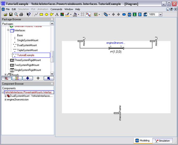
- We are creating a powertrain mounting system to support
two powertrain systems so we need to base our model on the
DualSystemMount Interface definition. Start by
extending this class
VehicleInterfaces.PowertrainMounts.Interfaces.DualSystemMount
- This interface definition contains 3 MultiBody connectors, the
one called chassisFrame will be attached to the
chassis subsystem in our vehicle model and is the chassis reference
frame. The other two connectors, mount_1 and
mount_2 are the reference frames for the two
subsystems that this mounting system will support. In this case
mount_1 will be treated as the engine reference
frame and mount_2 as the transmission reference
frame. The first step is to add a fixed translation
(Modelica.Mechanics.MultiBody.Parts.FixedTranslation)
between mount_1 and mount_2 to define the position of the
transmisison reference frame relative to the engine reference
frame.
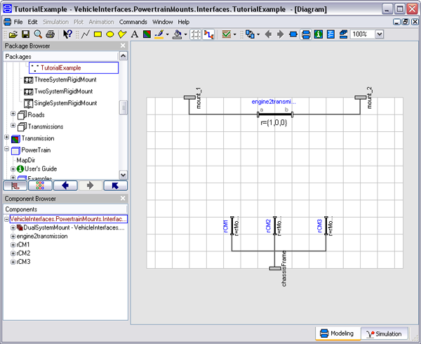
- The next step is to define the mounting system. In this example
we will utilise some components from the PowerTrain library to
define the mounting system. The engine and transmission systems
will be mounted by three elastic mounts. Start defining the
mounting system by adding three fixed translation blocks that
define the locations of the mounts relative to the
chassisFrame.
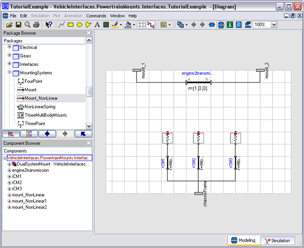
- Add the elastic mount blocks, in this case they are defined in
the PowerTrain library as
PowerTrain.MountingSystems.Mount
- Finally add 3 more fixed translation blocks that define the
location of the engine reference frame relative to each of the
mount locations.
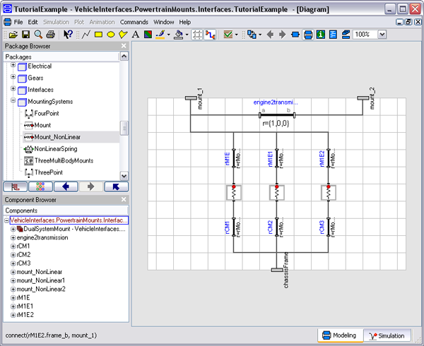
- The model is now complete and should check correctly
Generated at 2026-06-23T20:19:05Z by OpenModelicaOpenModelica 1.26.9 using
GenerateDoc.mos