
modelGuideline36
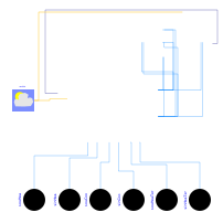
Extends from Modelica.Icons.Example (Icon for runnable examples), Buildings.Examples.VAVReheat.BaseClasses.HVACBuilding (Partial model that contains the HVAC and building model).
Information
This model consist of an HVAC system, a building envelope model and a model for air flow through building leakage and through open doors.
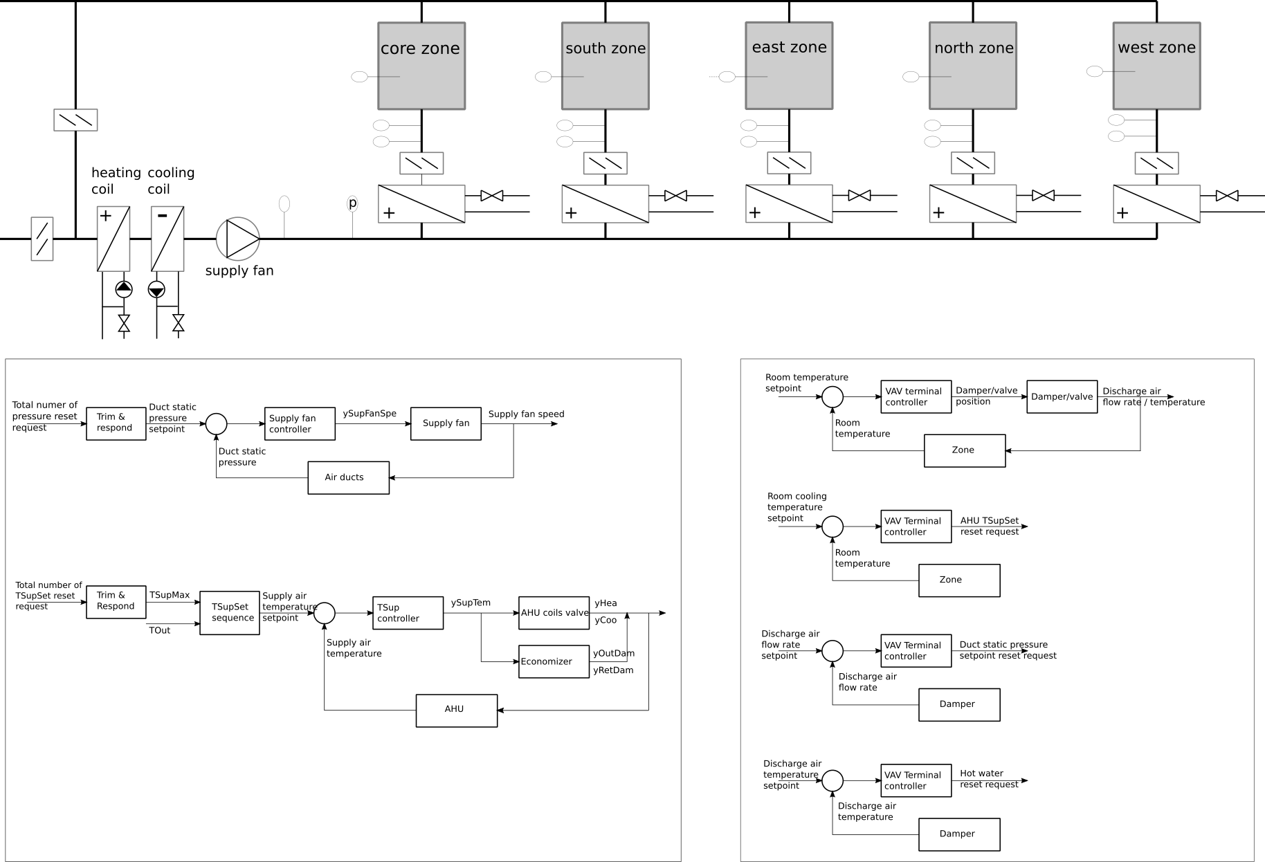
The HVAC system is a variable air volume (VAV) flow system with economizer and a heating and cooling coil in the air handler unit. There is also a reheat coil and an air damper in each of the five zone inlet branches.
See the model Buildings.Examples.VAVReheat.BaseClasses.PartialHVAC for a description of the HVAC system, and see the model Buildings.Examples.VAVReheat.BaseClasses.Floor for a description of the building envelope.
The control is based on ASHRAE Guideline 36, and implemented using the sequences from the library Buildings.Controls.OBC.ASHRAE.G36 for multi-zone VAV systems with economizer. The schematic diagram of the HVAC and control sequence is shown in the figure below.
A similar model but with a different control sequence can be found in Buildings.Examples.VAVReheat.ASHRAE2006. Note that this model, because of the frequent time sampling, has longer computing time than Buildings.Examples.VAVReheat.ASHRAE2006. The reason is that the time integrator cannot make large steps because it needs to set a time step each time the control samples its input.
Parameters
| Type | Name | Default | Description |
|---|---|---|---|
| Modelica.Units.SI.Volume | VRooCor (from HVACBuilding) | flo.VRooCor | Room volume corridor |
| Modelica.Units.SI.Volume | VRooSou (from HVACBuilding) | flo.VRooSou | Room volume south |
| Modelica.Units.SI.Volume | VRooNor (from HVACBuilding) | flo.VRooNor | Room volume north |
| Modelica.Units.SI.Volume | VRooEas (from HVACBuilding) | flo.VRooEas | Room volume east |
| Modelica.Units.SI.Volume | VRooWes (from HVACBuilding) | flo.VRooWes | Room volume west |
| Modelica.Units.SI.Area | AFloCor (from HVACBuilding) | flo.AFloCor | Floor area corridor |
| Modelica.Units.SI.Area | AFloSou (from HVACBuilding) | flo.AFloSou | Floor area south |
| Modelica.Units.SI.Area | AFloNor (from HVACBuilding) | flo.AFloNor | Floor area north |
| Modelica.Units.SI.Area | AFloEas (from HVACBuilding) | flo.AFloEas | Floor area east |
| Modelica.Units.SI.Area | AFloWes (from HVACBuilding) | flo.AFloWes | Floor area west |
| Real | conv (from HVACBuilding) | 1.2/3600 | Conversion factor for nominal mass flow rate |
| Modelica.Units.SI.MassFlowRate | mCor_flow_nominal (from HVACBuilding) | Design mass flow rate core | |
| Modelica.Units.SI.MassFlowRate | mSou_flow_nominal (from HVACBuilding) | Design mass flow rate south | |
| Modelica.Units.SI.MassFlowRate | mEas_flow_nominal (from HVACBuilding) | Design mass flow rate east | |
| Modelica.Units.SI.MassFlowRate | mNor_flow_nominal (from HVACBuilding) | Design mass flow rate north | |
| Modelica.Units.SI.MassFlowRate | mWes_flow_nominal (from HVACBuilding) | Design mass flow rate west | |
| Modelica.Units.SI.MassFlowRate[5] | mCooVAV_flow_nominal (from HVACBuilding) | {mSou_flow_nominal, mEas_flow_nominal, mNor_flow_nominal, mWes_flow_nominal, mCor_flow_nominal} | Design mass flow rate of each zone |
| Modelica.Units.SI.Temperature | THeaWatInl_nominal (from HVACBuilding) | 45 + 273.15 | Reheat coil nominal inlet water temperature |
| Real | ACHCor | 6 | Design air change per hour core |
| Real | ACHSou | 6 | Design air change per hour south |
| Real | ACHEas | 9 | Design air change per hour east |
| Real | ACHNor | 6 | Design air change per hour north |
| Real | ACHWes | 7 | Design air change per hour west |
Components
| Type | Name | Default | Description |
|---|---|---|---|
| Buildings.Examples.VAVReheat.BaseClasses.PartialHVAC | hvac (from HVACBuilding) | ||
| Buildings.Examples.VAVReheat.BaseClasses.PartialFloor | flo (from HVACBuilding) | ||
| Buildings.BoundaryConditions.WeatherData.ReaderTMY3 | weaDat (from HVACBuilding) | Weather data reader | |
| Fluid.Sources.Boundary_pT | sinHea (from HVACBuilding) | Sink for heating coil | |
| Fluid.Sources.Boundary_pT | souHea (from HVACBuilding) | Source for heating coil | |
| Fluid.Sources.Boundary_pT | sinCoo (from HVACBuilding) | Sink for cooling coil | |
| Fluid.Sources.Boundary_pT | souCoo (from HVACBuilding) | Source for cooling coil loop | |
| Fluid.Sources.Boundary_pT | souHeaTer (from HVACBuilding) | Source for heating of terminal boxes | |
| Fluid.Sources.Boundary_pT | sinHeaTer (from HVACBuilding) | Source for heating of terminal boxes |
Revisions
-
May 31, 2022, by Jianjun Hu:
First implementation.