
modelX3WithRadiantFloor
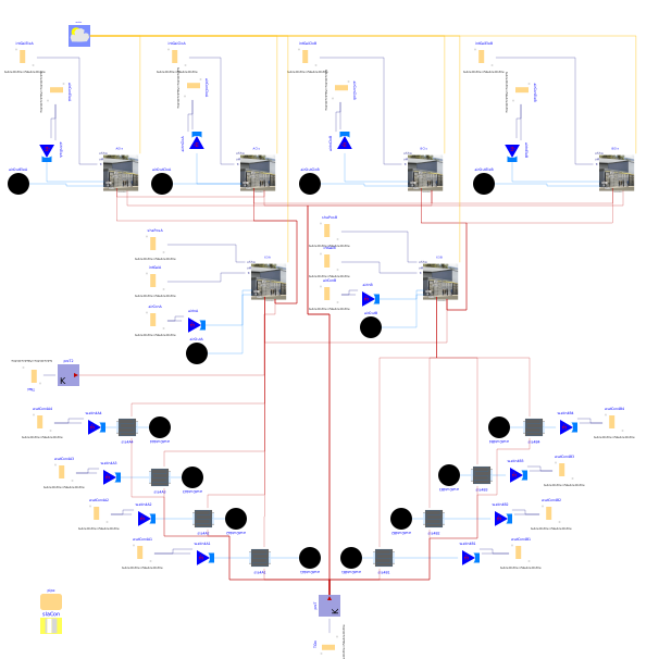
Example model of test cells X3A and X3B connected to form test bed X3
Extends from Modelica.Icons.Example (Icon for runnable examples).
Information
This example models demonstrates how the Buildings.ThermalZones.Detailed.FLEXLAB.Rooms.X3A and Buildings.ThermalZones.Detailed.FLEXLAB.Rooms.X3B test cell models can be combined to form a simulation of test bed X3. The example is primarily a combination of Buildings.ThermalZones.Detailed.FLEXLAB.Rooms.Examples.X3AWithRadiantFloor and Buildings.ThermalZones.Detailed.FLEXLAB.Rooms.Examples.X3BWithRadiantFloor. The example Buildings.ThermalZones.Detailed.FLEXLAB.Rooms.Examples.X3AWithRadiantFloor contains detailed documentation on these models. Some small changes were necessary to create the model of the test bed correctly. These changes are:
- To make the connection between X3A and X3B possible two of the models from the X3A example were replaced with models designed for connection to X3B.
- Connections between the two test cells do not exist in either of the other two examples.
- The data reader models in this example function in the same manner as in the
other two examples, but their names had to be changed to avoid using the same name
for multiple models in this example. Their names now contain a suffix describing the test
cell they're connected to. For example,
airConAis connected to test cell X3A andshaPosBis connected to test cell X3B. - TNei now only contains a temperature for test cell X2B. A temperature input for X3B is not needed because that test cell is now included in the model.
Parameters
| Type | Name | Default | Description |
|---|---|---|---|
| Buildings.HeatTransfer.Data.OpaqueConstructions.Generic | slaCon | Construction of the slab | |
| Buildings.Fluid.Data.Pipes.PEX_RADTEST | pipe |
Components
| Type | Name | Default | Description |
|---|---|---|---|
| Buildings.ThermalZones.Detailed.FLEXLAB.Rooms.X3B.TestCell | X3B | Test cell X3B | |
| Buildings.ThermalZones.Detailed.FLEXLAB.Rooms.X3B.Closet | BClo | Closet in test cell X3B | |
| Buildings.ThermalZones.Detailed.FLEXLAB.Rooms.X3B.Electrical | BEle | Electrical room in test cell X3B | |
| Buildings.ThermalZones.Detailed.FLEXLAB.Rooms.X3A.TestCellFullBed | X3A | Test cell X3A | |
| Buildings.ThermalZones.Detailed.FLEXLAB.Rooms.X3A.ClosetFullBed | AClo | Closet in test cell X3A | |
| Buildings.ThermalZones.Detailed.FLEXLAB.Rooms.X3A.Electrical | AEle | Electrical room in test cell X3A | |
| Buildings.BoundaryConditions.WeatherData.ReaderTMY3 | weaDat | ||
| Modelica.Blocks.Sources.CombiTimeTable | intGaiCloB | Internal gain heat flow for the closet in test cell X3B | |
| Modelica.Blocks.Sources.CombiTimeTable | intGaiCloA | Internal gain heat flow for the closet in test cell X3A | |
| Modelica.Blocks.Sources.CombiTimeTable | intGaiEleA | Internal gain heat flow for the electrical room in test cell X3A | |
| Modelica.Blocks.Sources.CombiTimeTable | intGaiEleB | Internal gain heat flow for the electrical room in test cell X3B | |
| Modelica.Blocks.Sources.CombiTimeTable | shaPosA | Position of the shade in test cell X3A | |
| Modelica.Blocks.Sources.CombiTimeTable | shaPosB | Position of the shade in test cell X3B | |
| Modelica.Blocks.Sources.CombiTimeTable | intGaiA | Internal gain heat flow in test cell X3A (Radiant = 1, Convective = 2, Latent = 3) | |
| Modelica.Blocks.Sources.CombiTimeTable | intGaiB | Internal gain heat flow in test cell X3B (Radiant = 1, Convective = 2, Latent = 3) | |
| Modelica.Blocks.Sources.CombiTimeTable | airConCloA | Inlet air conditions for the connected closet of test cell X3A (y[1] = m_flow, y[2] = T) | |
| Buildings.Fluid.Sources.MassFlowSource_T | airInCloA | Inlet air conditions (from AHU) for the closet of test cell X3A | |
| Buildings.Fluid.Sources.Boundary_pT | airOutCloA | Air outlet from the closet in test cell X3A | |
| Modelica.Blocks.Sources.CombiTimeTable | airConCloB | Inlet air conditions for the connected closet of test cell X3B (y[1] = m_flow, y[2] = T) | |
| Buildings.Fluid.Sources.MassFlowSource_T | airInCloB | Inlet air conditions (from AHU) for the closet of test cell X3B | |
| Buildings.Fluid.Sources.Boundary_pT | airOutCloB | Air outlet from the closet in test cell X3B | |
| Modelica.Blocks.Sources.CombiTimeTable | airConA | Inlet air conditions for test cell X3A (y[1] = m_flow, y[2] = T) | |
| Buildings.Fluid.Sources.MassFlowSource_T | airInA | Inlet air conditions (from AHU) for X3A | |
| Buildings.Fluid.Sources.Boundary_pT | airOutA | Air outlet for X3A | |
| Modelica.Blocks.Sources.CombiTimeTable | airConB | Inlet air conditions for test cell X3B (y[1] = m_flow, y[2] = T) | |
| Buildings.Fluid.Sources.MassFlowSource_T | airInB | Inlet air conditions (from AHU) for X3B | |
| Buildings.Fluid.Sources.Boundary_pT | airOutB | Air outlet for X3B | |
| Modelica.Blocks.Sources.CombiTimeTable | airConEleA | Inlet air conditions for the connected electrical room in test cell X3A (y[1] = m_flow, y[2] = T) | |
| Buildings.Fluid.Sources.MassFlowSource_T | airInEleA | Inlet air conditions (from AHU) for the electrical room in test cell X3A | |
| Buildings.Fluid.Sources.Boundary_pT | airOutEleA | Air outlet from the electrical room in test cell X3A | |
| Buildings.HeatTransfer.Sources.PrescribedTemperature | preT | Temperature of the ground | |
| Modelica.Blocks.Sources.CombiTimeTable | TGro | ||
| Modelica.Blocks.Sources.CombiTimeTable | TNei | Temperature of the neighboring test cells (y[1] = X2B) | |
| Buildings.HeatTransfer.Sources.PrescribedTemperature | preT2 | ||
| Buildings.Fluid.Sources.Boundary_pT | airOutEleB | Air outlet from the electrical room in test cell X3B | |
| Buildings.Fluid.Sources.MassFlowSource_T | airInEleB | Inlet air conditions (from AHU) for the electrical room in test cell X3B | |
| Modelica.Blocks.Sources.CombiTimeTable | airConEleB | Inlet air conditions for the connected electrical room in test cell X3B (y[1] = m_flow, y[2] = T) | |
| Buildings.Fluid.HeatExchangers.RadiantSlabs.SingleCircuitSlab | sla4A1 | Radiant slab serving the north side of cell X3A. Name is taken from drawing M3.02 | |
| Modelica.Blocks.Sources.CombiTimeTable | watCon4A1 | Inlet water conditions (y[1] = m_flow, y[2] = T) | |
| Buildings.Fluid.Sources.MassFlowSource_T | watIn4A1 | Inlet water conditions (from central plant) | |
| Modelica.Blocks.Sources.CombiTimeTable | watCon4A2 | Inlet water conditions (y[1] = m_flow, y[2] = T) | |
| Buildings.Fluid.Sources.MassFlowSource_T | watIn4A2 | Inlet water conditions (from central plant) | |
| Buildings.Fluid.HeatExchangers.RadiantSlabs.SingleCircuitSlab | sla4A2 | Radiant slab serving the north-central section of cell X3A. Name is taken from drawing M3.02 | |
| Buildings.Fluid.Sources.Boundary_pT | watOut4A2 | Water outlet | |
| Modelica.Blocks.Sources.CombiTimeTable | watCon4A3 | Inlet water conditions (y[1] = m_flow, y[2] = T) | |
| Buildings.Fluid.Sources.MassFlowSource_T | watIn4A3 | Inlet water conditions (from central plant) | |
| Buildings.Fluid.HeatExchangers.RadiantSlabs.SingleCircuitSlab | sla4A3 | Radiant slab serving the south-central section of cell X3A. Name is taken from drawing M3.02 | |
| Buildings.Fluid.Sources.Boundary_pT | watOut4A3 | Water outlet | |
| Modelica.Blocks.Sources.CombiTimeTable | watCon4A4 | Inlet water conditions (y[1] = m_flow, y[2] = T) | |
| Buildings.Fluid.Sources.MassFlowSource_T | watIn4A4 | Inlet water conditions (from central plant) | |
| Buildings.Fluid.HeatExchangers.RadiantSlabs.SingleCircuitSlab | sla4A4 | Radiant slab serving the south section of cell X3A. Name is taken from drawing M3.02 | |
| Buildings.Fluid.Sources.Boundary_pT | watOut4A4 | Water outlet | |
| Buildings.Fluid.Sources.Boundary_pT | watOut4A1 | Water outlet | |
| Modelica.Blocks.Sources.CombiTimeTable | watCon4B1 | Inlet water conditions (y[1] = m_flow, y[2] = T) | |
| Buildings.Fluid.Sources.MassFlowSource_T | watIn4B1 | Inlet water conditions (from central plant) | |
| Buildings.Fluid.HeatExchangers.RadiantSlabs.SingleCircuitSlab | sla4B1 | Radiant slab serving the north side of cell X3B. Name is taken from drawing M3.02 | |
| Buildings.Fluid.Sources.Boundary_pT | watOut4B1 | Water outlet | |
| Modelica.Blocks.Sources.CombiTimeTable | watCon4B2 | Inlet water conditions (y[1] = m_flow, y[2] = T) | |
| Buildings.Fluid.Sources.MassFlowSource_T | watIn4B2 | Inlet water conditions (from central plant) | |
| Buildings.Fluid.HeatExchangers.RadiantSlabs.SingleCircuitSlab | sla4B2 | Radiant slab serving the north-central section of cell X3B. Name is taken from drawing M3.02 | |
| Buildings.Fluid.Sources.Boundary_pT | watOut4B2 | Water outlet | |
| Modelica.Blocks.Sources.CombiTimeTable | watCon4B3 | Inlet water conditions (y[1] = m_flow, y[2] = T) | |
| Buildings.Fluid.Sources.MassFlowSource_T | watIn4B3 | Inlet water conditions (from central plant) | |
| Buildings.Fluid.HeatExchangers.RadiantSlabs.SingleCircuitSlab | sla4B3 | Radiant slab serving the south-central section of cell X3B. Name is taken from drawing M3.02 | |
| Buildings.Fluid.Sources.Boundary_pT | watOut4B3 | Water outlet | |
| Modelica.Blocks.Sources.CombiTimeTable | watCon4B4 | Inlet water conditions (y[1] = m_flow, y[2] = T) | |
| Buildings.Fluid.Sources.MassFlowSource_T | watIn4B4 | Inlet water conditions (from central plant) | |
| Buildings.Fluid.HeatExchangers.RadiantSlabs.SingleCircuitSlab | sla4B4 | Radiant slab serving the south section of cell X3B. Name is taken from drawing M3.02 | |
| Buildings.Fluid.Sources.Boundary_pT | watOut4B4 | Water outlet |
Contents
| Name | Description |
|---|---|
 Air Air | Air model used in the example model |
 Water Water | Water model used in the radiant slab loop |
Revisions
-
December 07, 2016, by Thierry S. Nouidui:
Changed example to place a state at the surface. -
August 23, 2016, by Thierry S. Nouidui:
Corrected the syntax of the weather data file name entry. -
April 21, 2016, by Michael Wetter:
ReplacedModelicaServices.ExternalReferences.loadResourcewithModelica.Utilities.Files.loadResource. -
December 22, 2014 by Michael Wetter:
RemovedModelica.Fluid.Systemto address issue #311. - September 2, 2014, by Michael Wetter:
Corrected wrong pipe diameter. - June 30, 2014, by Michael Wetter:
Specified equations to be used to compute the initial conditions. - October 11, 2013, by Michael Wetter:
Added missingparameterkeyword in the declaration of the data record. - Sep 19, 2013 by Peter Grant:
First implementation.