
modelHeatPumpRadiantHeatingGroundHeatTransfer
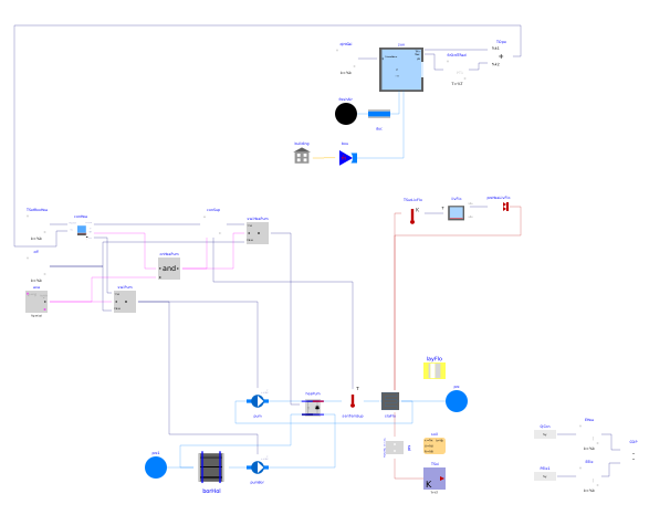
Extends from Buildings.ThermalZones.EnergyPlus_24_2_0.Examples.SingleFamilyHouse.Unconditioned (Example model with one unconditoned zone simulated in Modelica, and the other two unconditioned zones simulated in EnergyPlus).
Information
Model that uses EnergyPlus for the simulation of a building with one thermal zone that has a radiant floor, used for heating. The EnergyPlus model has one conditioned zone that is above ground. This conditioned zone has an unconditioned attic. Heating is provided with a geothermal heat pump and a radiant floor. The heat pump is controlled to track a set point of the water temperature that leaves the radiant slab. Hence, the control is cascading: First, the set point temperature for the water that leaves the radiant slab is calculated based on the operative room temperature control error, and this set point is used to regulate the heat pump speed to track the water temperature that leaves the radiant slab. The heat pump system is switched off from 5:00 to 7:00, which illustrates how to block operation for example because electricity use needs to be reduced during these hours. However, the model does not preheat the slab prior to this period.
To the right of the thermal zone is a block that computes the operative room temperature. The operative temperature calculation uses as input the room air temperature and the radiative temperature of the zone. The radiative temperature is fed into a first order filter before it is used to compute the operative temperature. This is because the EnergyPlus coupling samples the radiative temperature. Without this filter, the operative temperature used in the controller would have a discrete jump at every EnergyPlus time step, and this jump would be propagated through the controller, which would yield jumps in the output of the controller.
This model has no cooling and hence will overheat in summer. See Buildings.ThermalZones.EnergyPlus_24_2_0.Examples.SingleFamilyHouse.RadiantHeatingCooling_TRoom for a model that also has cooling.
The next section explains how the radiant floor is configured.
Coupling of radiant floor to EnergyPlus model
The radiant floor is modeled in the instance slaFlo at the bottom of the schematic model view,
using the model
Buildings.Fluid.HeatExchangers.RadiantSlabs.ParallelCircuitsSlab.
This instance models the heat transfer from surface of the floor to the lower surface of the slab.
In this example, the construction is defined by the instance layFlo.
(See the
Buildings.Fluid.HeatExchangers.RadiantSlabs.UsersGuide
for how to configure a radiant slab.)
In this example, the surface slaFlo.surf_a is connected to the instance
flo.
This connection is made by measuring the surface temperture, sending this as an input to
livFlo, and setting the heat flow rate at the surface from the instance livFlo
to the surface slaFlo.surf_a.
The underside of the slab is connected to the heat conduction model soi
which computes the heat transfer to the soil because this building has no basement.
Parameters
| Type | Name | Default | Description |
|---|---|---|---|
| Modelica.Units.SI.Volume | VRoo (from Unconditioned) | 453.1 | Room volume |
| Modelica.Units.SI.MassFlowRate | m_flow_nominal (from Unconditioned) | VRoo*1.2*0.3/3600 | Nominal mass flow rate |
| Modelica.Units.SI.Area | AFlo | 185.8 | Floor area |
| Modelica.Units.SI.HeatFlowRate | QHea_flow_nominal | 8000 | Nominal heat flow rate for heating |
| Modelica.Units.SI.MassFlowRate | mHea_flow_nominal | QHea_flow_nominal/4200/5 | Design water mass flow rate for heating |
| Modelica.Units.SI.MassFlowRate | mBor_flow_nominal | 2*mHea_flow_nominal*(1 - 1/4)*4200/3500 | Design water mass flow rate for heating |
| Buildings.HeatTransfer.Data.OpaqueConstructions.Generic | layFlo | Material layers from surface a to b (8cm concrete, 20 cm insulation, 20 cm concrete) | |
| Buildings.HeatTransfer.Data.Solids.Generic | soil | Soil properties |
Components
Contents
| Name | Description |
|---|---|
 MediumW MediumW | Water medium |
 MediumG MediumG | Water glycol |
Revisions
-
March 13, 2024, by Michael Wetter:
Updatedidffile to add insulation, and resized system.
This is for issue 3707. -
March 11, 2024, by Michael Wetter:
Corrected wrongdisplayUnitstring. -
December 1, 2022, by Michael Wetter:
Replaced idealized heating with geothermal heat pump, increased thickness of insulation of radiant slab, and changed pipe spacing. -
March 16, 2021, by Michael Wetter:
First implementation.