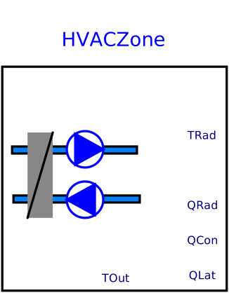
blockHVACZone
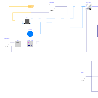
Extends from IBPSA.Fluid.FMI.ExportContainers.HVACZone (Partial block to export an HVAC system that has no radiative component and that serves multiple zones as an FMU).
Information
This example demonstrates how to export a model of an HVAC system that only provides convective cooling to a single thermal zone. The HVAC system is adapted from IBPSA.Examples.Tutorial.SpaceCooling.System3, but flow resistances have been added to have the same configuration as IBPSA.Fluid.FMI.ExportContainers.Examples.FMUs.HVACZones. Having the same configuration is needed for the validation test IBPSA.Fluid.FMI.ExportContainers.Validation.RoomHVAC.
The example extends from
IBPSA.Fluid.FMI.ExportContainers.HVACZone
which provides the input and output signals that are needed to interface
the acausal HVAC system model with causal connectors of FMI.
The instance hvacAda is the HVAC adapter
that contains on the left a fluid port, and on the right signal ports
which are then used to connect at the top-level of the model to signal
ports which are exposed at the FMU interface.
Parameters
| Type | Name | Default | Description |
|---|---|---|---|
| Real | eps | 0.8 | Heat recovery effectiveness |
| Modelica.SIunits.Temperature | TASup_nominal | 273.15 + 18 | Nominal air temperature supplied to room |
| Modelica.SIunits.Temperature | TRooSet | 273.15 + 24 | Nominal room air temperature |
| Modelica.SIunits.Temperature | TOut_nominal | 273.15 + 30 | Design outlet air temperature |
| Modelica.SIunits.Temperature | THeaRecLvg | TOut_nominal - eps*(TOut_nominal - TRooSet) | Air temperature leaving the heat recovery |
| Real | UA | 10E3 | Average UA-value of the room |
| Modelica.SIunits.HeatFlowRate | QRooInt_flow | 1000 | Internal heat gains of the room |
| Modelica.SIunits.HeatFlowRate | QRooC_flow_nominal | -QRooInt_flow - UA/30*(TOut_nominal - TRooSet) | Nominal cooling load of the room |
| Modelica.SIunits.MassFlowRate | mA_flow_nominal | 1.3*QRooC_flow_nominal/1006/(TASup_nominal - TRooSet) | Nominal air mass flow rate, increased by factor 1.3 to allow for recovery after temperature setback |
| Modelica.SIunits.TemperatureDifference | dTFan | 2 | Estimated temperature raise across fan that needs to be made up by the cooling coil |
| Modelica.SIunits.HeatFlowRate | QCoiC_flow_nominal | 4*(QRooC_flow_nominal + mA_flow_nominal*(TASup_nominal - THeaRecLvg - dTFan)*1006) | Cooling load of coil, taking into account economizer, and increased due to latent heat removal |
| Modelica.SIunits.Temperature | TWSup_nominal | 273.15 + 16 | Water supply temperature |
| Modelica.SIunits.Temperature | TWRet_nominal | 273.15 + 12 | Water return temperature |
| Modelica.SIunits.MassFlowRate | mW_flow_nominal | QCoiC_flow_nominal/(TWRet_nominal - TWSup_nominal)/4200 | Nominal water mass flow rate |
| Assumptions | |||
| Boolean | allowFlowReversal | false | = true to allow flow reversal, false restricts to design direction (inlet -> outlet) |
Connectors
| Type | Name | Default | Description |
|---|---|---|---|
| Interfaces.Outlet[size(hvacAda.fluPor, 1)] | fluPor (from HVACZone) | Fluid connector | |
| Modelica.Blocks.Interfaces.RealInput | TRadZon (from HVACZone) | Radiative temperature of the zone | |
| Modelica.Blocks.Interfaces.RealOutput | QGaiRad_flow (from HVACZone) | Radiant heat input into zone (positive if heat gain) | |
| Modelica.Blocks.Interfaces.RealOutput | QGaiSenCon_flow (from HVACZone) | Convective sensible heat input into zone (positive if heat gain) | |
| Modelica.Blocks.Interfaces.RealOutput | QGaiLat_flow (from HVACZone) | Latent heat input into zone (positive if heat gain) | |
| BoundaryConditions.WeatherData.Bus | weaBus | Weather data bus | |
| Modelica.Blocks.Interfaces.RealOutput | TOut | Outdoor temperature |
Components
| Type | Name | Default | Description |
|---|---|---|---|
| Adaptors.HVAC | hvacAda (from HVACZone) | Adapter between the HVAC supply and return air, and its connectors for the FMU | |
| Modelica.Blocks.Sources.Constant | zero | Zero output signal | |
| Movers.FlowControlled_m_flow | fan | Supply air fan | |
| HeatExchangers.ConstantEffectiveness | hex | Heat recovery | |
| IBPSA.Fluid.HeatExchangers.ConstantEffectiveness | cooCoi | ||
| IBPSA.Fluid.Sources.Outside | out | Outside air boundary condition | |
| Sources.MassFlowSource_T | souWat | Source for water flow rate | |
| Sources.FixedBoundary | sinWat | Sink for water circuit | |
| Modelica.Blocks.Sources.Constant | mAir_flow | Fan air flow rate | |
| Sensors.TemperatureTwoPort | senTemHXOut | Temperature sensor for heat recovery outlet on supply side | |
| Sensors.TemperatureTwoPort | senTemSupAir | Temperature sensor for supply air | |
| Modelica.Blocks.Logical.OnOffController | con | Controller for coil water flow rate | |
| Modelica.Blocks.Sources.Constant | TRooSetPoi | Room temperature set point | |
| Modelica.Blocks.Math.BooleanToReal | mWat_flow | Conversion from boolean to real for water flow rate | |
| BoundaryConditions.WeatherData.ReaderTMY3 | weaDat | Weather data reader | |
| FixedResistances.PressureDrop | resSup1 | Fixed resistance for supply air inlet | |
| FixedResistances.PressureDrop | resRet1 | Fixed resistance for return air duct |
Contents
| Name | Description |
|---|---|
 MediumA MediumA | Medium for air |
 MediumW MediumW | Medium for water |
Revisions
-
November 11, 2016, by Michael Wetter:
Made the cooling coil replaceable because the Buildings library uses the model for validation with a cooling coil model that is not in the Annex 60 library. -
April 16, 2016 by Michael Wetter:
First implementation.