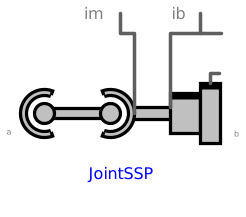
modelJointSSP
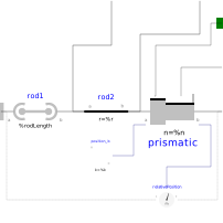
Extends from Interfaces.PartialTwoFramesDoubleSize (Base model for components providing two frame connectors + outer world + assert to guarantee that the component is connected (default icon size is factor 2 larger as usual)).
Information
This component consists of a spherical joint 1 at frame_a, a prismatic joint at frame_b and a spherical joint 2 which is connected via rod 1 to the spherical joint 1 and via rod 2 to the prismatic joint, see the default animation in the following figure (the axes vectors are not part of the default animation):
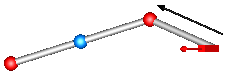
Besides an optional point mass in the middle of rod 1, this joint aggregation has no mass and no inertia, and introduces neither constraints nor potential state variables. It should be used in kinematic loops whenever possible since the non-linear system of equations introduced by this joint aggregation is solved analytically (i.e., a solution is always computed, if a unique solution exists).
An additional frame_ib is present. It is fixed in rod 2 connecting the prismatic and the spherical joint at the side of the prismatic joint that is connected to this rod (= rod2.frame_a = prismatic.frame_a).
An additional frame_im is present. It is fixed in rod 2 connecting the prismatic and the spherical joint at the side of spherical joint 2 that is connected to this rod (= rod2.frame_b). It is always parallel to frame_ib.
The easiest way to define the parameters of this joint is by moving the MultiBody system in a reference configuration where all frames of all components are parallel to each other (alternatively, at least frame_b and frame_ib of the JointSSP joint should be parallel to each other when defining an instance of this component).
Parameters
| Type | Name | Default | Description |
|---|---|---|---|
| Boolean | animation | true | = true, if animation shall be enabled |
| Boolean | showMass | true | = true, if point mass on rod 1 shall be shown (provided animation = true and rod1Mass > 0) |
| SI.Length | rod1Length | Distance between the origins of the two spherical joints | |
| SI.Mass | rod1Mass | 0 | Mass of rod 1 (= point mass located in middle of rod connecting the two spherical joints) |
| Modelica.Mechanics.MultiBody.Types.Axis | n_b | {0, 0, 1} | Axis of prismatic joint fixed and resolved in frame_b |
| SI.Position[3] | rRod2_ib | {1, 0, 0} | Vector from origin of frame_ib to spherical joint in the middle, resolved in frame_ib |
| SI.Position | s_offset | 0 | Relative distance offset of prismatic joint (distance between frame_b and frame_ib = s(t) + s_offset) |
| SI.Position | s_guess | 0 | Select the configuration such that at initial time |s(t0)-s_guess| is minimal |
| Animation › if animation = true | |||
| SI.Diameter | sphereDiameter | world.defaultJointLength | Diameter of the spheres representing the two spherical joints |
| SI.Diameter | rod1Diameter | sphereDiameter/Types.Defaults.JointRodDiameterFraction | Diameter of rod 1 connecting the two spherical joints |
| SI.Diameter | rod2Diameter | rod1Diameter | Diameter of rod 2 connecting the revolute joint and spherical joint 2 |
| Types.Axis | boxWidthDirection | {0, 1, 0} | Vector in width direction of prismatic joint box, resolved in frame_b |
| SI.Distance | boxWidth | world.defaultJointWidth | Width of prismatic joint box |
| SI.Distance | boxHeight | boxWidth | Height of prismatic joint box |
| Advanced | |||
| Boolean | checkTotalPower | false | = true, if total power flowing into this component shall be determined (must be zero) |
Connectors
| Type | Name | Default | Description |
|---|---|---|---|
| Interfaces.Frame_a | frame_a (from PartialTwoFramesDoubleSize) | Coordinate system fixed to the component with one cut-force and cut-torque | |
| Interfaces.Frame_b | frame_b (from PartialTwoFramesDoubleSize) | Coordinate system fixed to the component with one cut-force and cut-torque | |
| Modelica.Mechanics.MultiBody.Interfaces.Frame_b | frame_ib | Coordinate system at origin of frame_b fixed at connecting rod of spherical and prismatic joint | |
| Modelica.Mechanics.MultiBody.Interfaces.Frame_b | frame_im | Coordinate system at origin of spherical joint in the middle fixed at connecting rod of spherical and prismatic joint | |
| Modelica.Mechanics.Translational.Interfaces.Flange_a | axis | 1-dim. translational flange that drives the prismatic joint | |
| Modelica.Mechanics.Translational.Interfaces.Flange_b | bearing | 1-dim. translational flange of the drive bearing of the prismatic joint |
Components
| Type | Name | Default | Description |
|---|---|---|---|
| Types.Color | sphereColor | Modelica.Mechanics.MultiBody.Types.Defaults.JointColor | Color of the spheres representing the two spherical joints |
| Types.Color | rod1Color | Modelica.Mechanics.MultiBody.Types.Defaults.RodColor | Color of rod 1 connecting the two spherical joint |
| Types.Color | rod2Color | rod1Color | Color of rod 2 connecting the revolute joint and spherical joint 2 |
| Types.Color | boxColor | Modelica.Mechanics.MultiBody.Types.Defaults.JointColor | Color of prismatic joint box |
| Types.SpecularCoefficient | specularCoefficient | world.defaultSpecularCoefficient | Reflection of ambient light (= 0: light is completely absorbed) |
| Real | aux | Denominator used to compute force in rod connecting universal and spherical joint | |
| SI.Force | f_rod | Constraint force in direction of the rod (positive, if rod is pressed) | |
| SI.Power | totalPower | Total power flowing into this element, if checkTotalPower=true (otherwise dummy) | |
| Modelica.Mechanics.MultiBody.Joints.Internal.PrismaticWithLengthConstraint | prismatic | ||
| Modelica.Mechanics.MultiBody.Joints.SphericalSpherical | rod1 | ||
| Modelica.Mechanics.MultiBody.Parts.FixedTranslation | rod2 | ||
| Sensors.RelativePosition | relativePosition | ||
| Modelica.Blocks.Sources.Constant[3] | position_b |