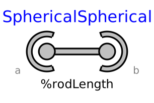
modelSphericalSpherical

Extends from Interfaces.PartialTwoFrames (Base model for components providing two frame connectors + outer world + assert to guarantee that the component is connected).
Information
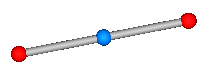
Joint that has a spherical joint on each of its two ends. The rod connecting the two spherical joints is approximated by a point mass that is located in the middle of the rod. When the mass is set to zero (default), special code for a massless body is generated. In the following default animation figure, the two spherical joints are represented by two red spheres, the connecting rod by a grey cylinder and the point mass in the middle of the rod by a light blue sphere:
This joint introduces one constraint defining that the distance between the origin of frame_a and the origin of frame_b is constant (= rodLength). It is highly recommended to use this joint in loops whenever possible, because this enhances the efficiency considerably due to smaller systems of non-linear algebraic equations.
It is sometimes desirable to compute the rodLength of the connecting rod during initialization. For this, parameter computeLength has to be set to true and instead one other, easier to determine, position variable in the same loop needs to have a fixed attribute of true. For example, if a loop consists of one Revolute joint, one Prismatic joint and a SphericalSpherical joint, one may fix the start values of the revolute joint angle and of the relative distance of the prismatic joint in order to compute the rodLength of the rod.
It is not possible to connect other components, such as a body with mass properties or a special visual shape object to the rod connecting the two spherical joints. If this is needed, use instead joint Joints.UniversalSpherical that has this property.
Parameters
| Type | Name | Default | Description |
|---|---|---|---|
| Boolean | animation | true | = true, if animation shall be enabled |
| Boolean | showMass | true | = true, if mass shall be shown (provided animation = true and m > 0) |
| Boolean | computeRodLength | false | = true, if rodLength shall be computed during initialization (see info) |
| SI.Length | rodLength | Distance between the origins of frame_a and frame_b (if computeRodLength=true, guess value) | |
| SI.Mass | m | 0 | Mass of rod (= point mass located in middle of rod) |
| Animation › if animation = true | |||
| SI.Diameter | sphereDiameter | world.defaultJointLength | Diameter of spheres representing the spherical joints |
| SI.Diameter | rodDiameter | sphereDiameter/Types.Defaults.JointRodDiameterFraction | Diameter of rod connecting the two spherical joint |
| Animation › if animation = true and showMass = true and m > 0 | |||
| SI.Diameter | massDiameter | sphereDiameter | Diameter of sphere representing the mass point |
| Advanced | |||
| Boolean | kinematicConstraint | true | = false, if no constraint shall be defined, due to analytically solving a kinematic loop ("false" should not be used by user, but only by MultiBody.Joints.Assemblies joints) |
| Boolean | checkTotalPower | false | = true, if total power flowing into this component shall be determined (must be zero) |
Connectors
| Type | Name | Default | Description |
|---|---|---|---|
| Interfaces.Frame_a | frame_a (from PartialTwoFrames) | Coordinate system a fixed to the component with one cut-force and cut-torque | |
| Interfaces.Frame_b | frame_b (from PartialTwoFrames) | Coordinate system b fixed to the component with one cut-force and cut-torque |
Components
| Type | Name | Default | Description |
|---|---|---|---|
| Types.Color | sphereColor | Modelica.Mechanics.MultiBody.Types.Defaults.JointColor | Color of spheres representing the spherical joints |
| Types.Color | rodColor | Modelica.Mechanics.MultiBody.Types.Defaults.RodColor | Color of rod connecting the two spherical joints |
| Types.Color | massColor | Modelica.Mechanics.MultiBody.Types.Defaults.BodyColor | Color of sphere representing the mass point |
| Types.SpecularCoefficient | specularCoefficient | world.defaultSpecularCoefficient | Reflection of ambient light (= 0: light is completely absorbed) |
| Real | constraintResidue | rRod_0*rRod_0 - rodLength*rodLength | Constraint equation of joint in residue form: Either length constraint (= default) or equation to compute rod force (for analytic solution of loops in combination with Internal.RevoluteWithLengthConstraint/PrismaticWithLengthConstraint) |
| SI.Force | f_rod | Constraint force in direction of the rod (positive on frame_a, when directed from frame_a to frame_b) | |
| SI.Position[3] | rRod_0 | Position vector from frame_a to frame_b resolved in world frame | |
| SI.Position[3] | rRod_a | Position vector from frame_a to frame_b resolved in frame_a | |
| Real[3] | eRod_a | Unit vector in direction from frame_a to frame_b, resolved in frame_a | |
| SI.Position[3] | r_CM_0 | Dummy if m==0, or position vector from world frame to mid-point of rod, resolved in world frame | |
| SI.Velocity[3] | v_CM_0 | First derivative of r_CM_0 | |
| SI.Force[3] | f_CM_a | Dummy if m==0, or inertial force acting at mid-point of rod due to mass point acceleration, resolved in frame_a | |
| SI.Force[3] | f_CM_e | Dummy if m==0, or projection of f_CM_a onto eRod_a, resolved in frame_a | |
| SI.Force[3] | f_b_a1 | Force acting at frame_b, but without force in rod, resolved in frame_a | |
| SI.Power | totalPower | Total power flowing into this element, if checkTotalPower=true (otherwise dummy) |