
modelClosedLoop
Extends from Modelica.Icons.Example (Icon for runnable examples).
Information
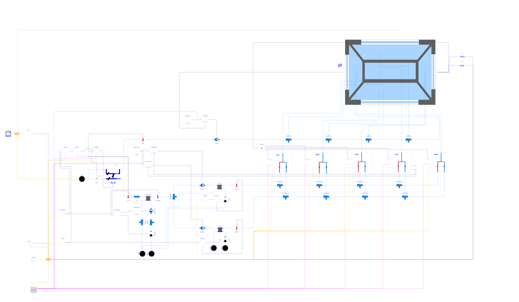
This model consist of an HVAC system, a building envelope model and a model for air flow through building leakage and through open doors.
The HVAC system is a dual-fan, dual-duct system with economizer and a heating and cooling coil in the air handler unit. One of the supply air streams is called the hot-deck and has a heating coil, the other is called the cold-deck and has a cooling coil. There is also one return fan and an economizer. The figure below shows the schematic diagram of the dual-fan, dual-duct system.
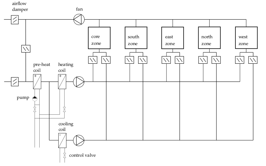
Each thermal zone inlet branch has a flow mixer and an air damper in the hot deck and the cold deck. The air damper control signals are as shown in the figure below.
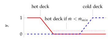
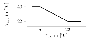
Hence, at low room temperatures, the amount of hot air is increased, and at high room temperatures, the amount of cold air is increased. In addition, whenever the air mass flow rate is below a prescribed limit, the hot air deck damper opens to track the minimum air flow rate. The temperature of the hot-deck is reset based on the outside air temperature. The temperature of the cold-deck is constant. The revolutions of both supply fans are controlled in order to track a pressure difference between VAV damper inlet and room pressure of 30 Pascals. The return fan is controlled to track a building pressure of 30 Pascals above outside air pressure. There is also an economizer which is controlled to provide the following functions: freeze protection, minimum outside air requirement, and supply air cooling, see Buildings.Examples.VAVReheat.BaseClasses.Controls.Economizer. During night-time, the fans are switched off. The coils are controlled as follows: The preheat coil is controlled to maintain an air outlet temperature of 11°C during day-time, and 6°C during night-time. The heating coil is controlled to maintain the air outlet temperature shown in the figure below.
The cooling coil is controlled to maintain a constant outlet temperature of 12° during day-time, and 40°C during night-time
There is also a finite state machine that transitions the mode of operation of the HVAC system between the modes occupied, unoccupied off, unoccupied night set back, unoccupied warm-up and unoccupied pre-cool.
All air flows are computed based on the duct static pressure distribution and the performance curves of the fans. Local loop control is implemented using proportional and proportional-integral controllers, while the supervisory control is implemented using a finite state machine.
To model the heat transfer through the building envelope, a model of five interconnected rooms is used. The five room model is representative of one floor of the new construction medium office building for Chicago, IL, as described in the set of DOE Commercial Building Benchmarks (Deru et al, 2009). There are four perimeter zones and one core zone. The envelope thermal properties meet ASHRAE Standard 90.1-2004. The thermal room model computes transient heat conduction through walls, floors and ceilings and long-wave radiative heat exchange between surfaces. The convective heat transfer coefficient is computed based on the temperature difference between the surface and the room air. There is also a layer-by-layer short-wave radiation, long-wave radiation, convection and conduction heat transfer model for the windows. The model is similar to the Window 5 model and described in TARCOG 2006.
Each thermal zone can have air flow from the HVAC system, through leakages of the building envelope (except for the core zone) and through bi-directional air exchange through open doors that connect adjacent zones. The bi-directional air exchange is modeled based on the differences in static pressure between adjacent rooms at a reference height plus the difference in static pressure across the door height as a function of the difference in air density. There is also wind pressure acting on each facade. The wind pressure is a function of the wind speed and wind direction. Therefore, infiltration is a function of the flow imbalance of the HVAC system and of the wind conditions.
References
ASHRAE. Sequences of Operation for Common HVAC Systems. ASHRAE, Atlanta, GA, 2006.
Deru M., K. Field, D. Studer, K. Benne, B. Griffith, P. Torcellini, M. Halverson, D. Winiarski, B. Liu, M. Rosenberg, J. Huang, M. Yazdanian, and D. Crawley. DOE commercial building research benchmarks for commercial buildings. Technical report, U.S. Department of Energy, Energy Efficiency and Renewable Energy, Office of Building Technologies, Washington, DC, 2009.
TARCOG 2006: Carli, Inc., TARCOG: Mathematical models for calculation of thermal performance of glazing systems with our without shading devices, Technical Report, Oct. 17, 2006.
Parameters
| Type | Name | Default | Description |
|---|---|---|---|
| Real | yFan_start | 0.0 | Initial or guess value of output (= state) |
| Boolean | from_dp | true | = true, use m_flow = f(dp) else dp = f(m_flow) |
| Boolean | linearizeFlowResistance | false | = true, use linear relation between m_flow and dp for any flow rate |
| Modelica.Units.SI.Volume | VRooCor | 2698 | Room volume corridor |
| Modelica.Units.SI.Volume | VRooSou | 568.77 | Room volume south |
| Modelica.Units.SI.Volume | VRooNor | 568.77 | Room volume north |
| Modelica.Units.SI.Volume | VRooEas | 360.08 | Room volume east |
| Modelica.Units.SI.Volume | VRooWes | 360.08 | Room volume west |
| Real | conv | 1.2/3600 | Conversion factor for nominal mass flow rate |
| Modelica.Units.SI.MassFlowRate | m0_flow_cor | 3*VRooCor*conv | Design mass flow rate core |
| Modelica.Units.SI.MassFlowRate | m0_flow_sou | 8*VRooSou*conv | Design mass flow rate perimeter 1 |
| Modelica.Units.SI.MassFlowRate | m0_flow_eas | 9*VRooEas*conv | Design mass flow rate perimeter 2 |
| Modelica.Units.SI.MassFlowRate | m0_flow_nor | 11*VRooNor*conv | Design mass flow rate perimeter 3 |
| Modelica.Units.SI.MassFlowRate | m0_flow_wes | 10*VRooWes*conv | Design mass flow rate perimeter 4 |
| Modelica.Units.SI.MassFlowRate | m_flow_nominal | m0_flow_cor + m0_flow_sou + m0_flow_eas + m0_flow_nor + m0_flow_wes | Nominal air mass flow rate |
| Modelica.Units.SI.MassFlowRate | mAirOut_flow_nominal | 0.3*m_flow_nominal | Nominal outside air mass flow rate |
| Modelica.Units.SI.MassFlowRate | mAirHot_flow_nominal | 0.3*m_flow_nominal | Nominal air mass flow rate for hot deck |
| Modelica.Units.SI.MassFlowRate | mAirCol_flow_nominal | m_flow_nominal | Nominal air mass flow rate for cold deck |
| Modelica.Units.SI.MassFlowRate | mWatPre_flow_nominal | (TMixHea_nominal - 273.15 - (-20))*1000/15/4200*mAirOut_flow_nominal | Nominal water mass flow rate for preheat coil |
| Modelica.Units.SI.MassFlowRate | mWatCol_flow_nominal | (28 - 13)*1000*1.3/4200/15*mAirCol_flow_nominal | Nominal water mass flow rate for cooling coil of cold deck |
| Modelica.Units.SI.MassFlowRate | mWatHot_flow_nominal | (40 - (TMixHea_nominal - 273.15))*1000/15/4200*mAirHot_flow_nominal | Nominal water mass flow rate for heating coil of cold deck |
| Modelica.Units.SI.Temperature | TMixHea_nominal | 0.3*(273.15 + (-20)) + 0.7*(273.15 + 20) | Mixed air temperature at winter design conditions |
| Modelica.Units.SI.Temperature | TMixCoo_nominal | 0.3*(273.15 + (33)) + 0.7*(273.15 + 26) | Mixed air temperature at summer design conditions |
| Modelica.Units.SI.Temperature | TSupCol_nominal | 12 + 273.15 | Cold deck temperature at nominal condition |
Connectors
| Type | Name | Default | Description |
|---|---|---|---|
| Buildings.Examples.VAVReheat.BaseClasses.Controls.ControlBus | controlBus | ||
| BoundaryConditions.WeatherData.Bus | weaBus | Weather Data Bus |
Components
Contents
| Name | Description |
|---|---|
 MediumA MediumA | |
 MediumW MediumW | Medium model for water |
Revisions
-
March 4, 2024, by Michael Wetter:
Corrected wrong use ofdisplayUnitattribute. -
August 22, 2022, by Hongxiang Fu:
ReplacedfanSupColandfanRetwith preconfigured fan models. This is for issue #2668. -
September 16, 2021, by Michael Wetter:
Removed assignment of parameterlatas this is now obtained from the weather data reader.
This is for IBPSA, #1477. -
June 30, 2021, by Antoine Gautier:
Changed cooling coil model. This is for issue #2549. -
October 27, 2020, by Antoine Gautier:
Refactored the model for compatibility with the updated control of supply air temperature. This is for #2024. -
July 11, 2019, by Michael Wetter:
Changed wrong assignment of air-side nominal flow rate of preheat coil. Moved air-side flow resistance of preheat coil to filter model to reduce the dimension of the nonlinear equations. -
November 17, 2017, by Michael Wetter:
Enabled filters at fan control signal. This avoids a sharp change in fan speed, which led to very large mass flow rates between the hot and cold deck fan when they were switched off. This model now works with JModelica with the CVode solver and 10-8 tolerance. -
May 19, 2016, by Michael Wetter:
Setuse_inputFilter=falsein fan models to avoid a large increase in computing time when simulated between t=1.60E7 and t=1.66E7. -
April 26, 2016, by Michael Wetter:
Changed controller for freeze protection as the old implementation closed the outdoor air damper during summer. This is for #511. -
March 1, 2016, by Michael Wetter:
Removed parameterdynamicBalanceJunctionandenergyDynamicsJunction. -
September 24, 2015 by Michael Wetter:
Set default temperature for medium to avoid conflicting start values for alias variables of the temperature of the building and the ambient air. This is for issue 426. -
June 10, 2015, by Michael Wetter:
In air handler unit, changed all coil controllers to proportional controllers, set the proportional band to 1 Kelvin, and removed the raise time of the coil valves. This leads to more stable control. Previously, the raise time was 120 seconds, and there was a PI controller with time constant of 120 seconds, which caused oscillatory behavior in the heating coil. -
March 2, 2015, by Michael Wetter:
Added resistance of preheat coil to filter, changed controller of return fan to use a PI controller. This was done to stabilize the control during summer. -
December 22, 2014 by Michael Wetter:
RemovedModelica.Fluid.Systemto address issue #311. -
December 6, 2011, by Michael Wetter:
Improved control for minimum zone flow rate. -
July 18, 2011, by Michael Wetter:
First implementation.