modelPlanar
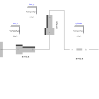
Extends from Modelica.Mechanics.MultiBody.Interfaces.PartialTwoFrames (Base model for components providing two frame connectors + outer world + assert to guarantee that the component is connected).
Information
Joint where frame_b can move in a plane and can rotate around an axis orthogonal to the plane. The plane is defined by vector n which is perpendicular to the plane and by vector n_x, which points in the direction of the x-axis of the plane. frame_a and frame_b coincide when s_x=prismatic_x.s=0, s_y=prismatic_y.s=0 and phi=revolute.phi=0. This joint has the following potential states:
- the relative distance s_x = prismatic_x.s [m] along axis n_x,
- the relative distance s_y = prismatic_y.s [m] along axis n_y = cross(n,n_x),
- the relative angle phi = revolute.phi [rad] around axis n,
- the relative velocity v_x (= der(s_x)).
- the relative velocity v_y (= der(s_y)).
- the relative angular velocity w (= der(phi))
They are used as candidates for automatic selection of states from the tool. This may be enforced by setting "stateSelect=StateSelect.always" in the Advanced menu. The states are usually selected automatically. In certain situations, especially when closed kinematic loops are present, it might be slightly more efficient, when using the "StateSelect.always" setting.
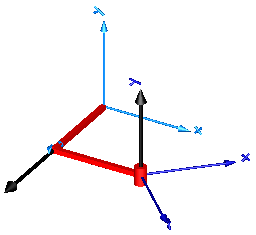
In the following figure the animation of a planar joint is shown. The light blue coordinate system is frame_a and the dark blue coordinate system is frame_b of the joint. The black arrows are parameter vectors "n" and "n_x" (here: n = {0,1,0}, n_x = {0,0,1}, s_x.start = 0.5, s_y.start = 0.5, phi.start = 45o).
Parameters
| Type | Name | Default | Description |
|---|---|---|---|
| Boolean | animation | true | = true, if animation shall be enabled |
| Modelica.Mechanics.MultiBody.Types.Axis | n | {0, 0, 1} | Axis orthogonal to unconstrained plane, resolved in frame_a (= same as in frame_b) |
| Modelica.Mechanics.MultiBody.Types.Axis | n_x | {1, 0, 0} | Vector in direction of x-axis of plane, resolved in frame_a (n_x shall be orthogonal to n) |
| Animation › if animation = true | |||
| SI.Distance | cylinderLength | world.defaultJointLength | Length of revolute cylinder |
| SI.Distance | cylinderDiameter | world.defaultJointWidth | Diameter of revolute cylinder |
| SI.Distance | boxWidth | 0.3*cylinderDiameter | Width of prismatic joint boxes |
| SI.Distance | boxHeight | boxWidth | Height of prismatic joint boxes |
| Advanced | |||
| StateSelect | stateSelect | StateSelect.prefer | Priority to use joint coordinates (s_x, s_y, phi, v_x, v_y, w) as states |
Connectors
| Type | Name | Default | Description |
|---|---|---|---|
| Interfaces.Frame_a | frame_a (from PartialTwoFrames) | Coordinate system a fixed to the component with one cut-force and cut-torque | |
| Interfaces.Frame_b | frame_b (from PartialTwoFrames) | Coordinate system b fixed to the component with one cut-force and cut-torque |
Components
| Type | Name | Default | Description |
|---|---|---|---|
| Types.Color | cylinderColor | Modelica.Mechanics.MultiBody.Types.Defaults.JointColor | Color of revolute cylinder |
| Types.Color | boxColor | Modelica.Mechanics.MultiBody.Types.Defaults.JointColor | Color of prismatic joint boxes |
| Prismatic | prismatic_x | ||
| Prismatic | prismatic_y | ||
| Revolute | revolute | ||
| SI.Position | s_x | Relative distance along first prismatic joint starting at frame_a | |
| SI.Position | s_y | Relative distance along second prismatic joint starting at first prismatic joint | |
| SI.Angle | phi | Relative rotation angle from frame_a to frame_b | |
| SI.Velocity | v_x | First derivative of s_x (relative velocity in s_x direction) | |
| SI.Velocity | v_y | First derivative of s_y (relative velocity in s_y direction) | |
| SI.AngularVelocity | w | First derivative of angle phi (relative angular velocity) | |
| SI.Acceleration | a_x | Second derivative of s_x (relative acceleration in s_x direction) | |
| SI.Acceleration | a_y | Second derivative of s_y (relative acceleration in s_y direction) | |
| SI.AngularAcceleration | wd | Second derivative of angle phi (relative angular acceleration) |